|
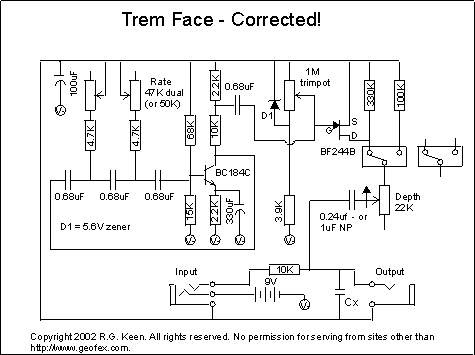
Here's how it works: The BC184C NPN transistor is set up as a phase shift oscillator. The signal from its collector is routed through three C-R phase shift networks - those 0.68uF caps and the resistors to ground between them. Two of the resistors to ground are adjustable. Those are the two legs with a 4.7K resistor in series with sections of the dual pot. The third is fixed; the resistance there is the parallel combination of the 15K and 68K biasing resistors on the transistor. The phase shift introduced by the caps is enough at some frequency to cause a signal at the collector to be in phase, not inverted, from the signal at the collector, so at that frequency the feedback is positive, and oscillations happen. Changing the two resistances changes the frequency at which this happens, and therefore the frequency of oscillation. A portion of the signal at the collector of the NPN is tapped off the collector at the junction of the 10K and 2.2K resistors and fed through a capacitor to the gate of the BF244. This imposes the oscillator signal on top of whatever DC level is at the JFET gate. The JFET gate is biased to a DC level determined by the zener diode voltage and the setting of the trimpot. I flatly guessed at the value of the zener voltage, based on the pinchoff voltage of the JFET specs. With a 5V zener, you should be able to trim in any BF244B that is within spec. The DC level can then be between 0V and -5V compared to the source of the JFET. With 0V DC on the drain of the JFET, it's acting like a variable resistor. The zener turned out to be 5.7V, a very common value.
The JFET drain resistance can vary over a huge range - infinity (off) down to hundreds of ohms. The signal goes through the series 10K resistor from input to output, but the output is shunted to ground by a variable resistance. This is the resistance of the JFET in series with whatever the setting of the depth pot is. With the JFET resistance over 100K, there is no appreciable signal loss. The "bypass" just sets the signal loss to a factor of about 120/130, less than 1db and practically inaudible, especially with no standard signal to compare it to. This is very similar in concept to other tremolos, such as the EAN tremolo, the Diaz Tremadillo, and several others. |
