Lots of folks want to make their own effects, but don't have a good way or the experience to do a layout or to make the boards, even with the aid of an iron on toner sheet. To help with this, I laid out and had etched and drilled PCB's for some effects I've made for myself.
RTS board Packages
The boards are already etched and drilled, and are the exact same pattern as the ones in the toner packages, just already etched and drilled, ready to start mounting parts onto. The boards are all designed to fit well within a Hammond die cast box, and to be easy to wire to controls, etc. Each RTS board package includes full documentation for how to complete the effect, including parts list, suppliers for parts, how it works, schematic, parts placement on the board, and wiring diagram for hooking up switches, jacks, controls, etc. The information packages that come with the RTS board package is exactly the same as the information that comes with the Toner Packages and Board Kits. The exception is for boards that are supported by the discussions at Aron Nelson's stompbox forum. For those, you can download the single sheet directions from GEO directly, and support is through the discussion board.
I used to lay out PCB's for a living a long time ago, so the layouts are of good quality and not awkward to use and wire.
Each of these layouts have been built and tested, and they are known to work if built correctly with the right parts.
I get asked all the time whether the RTS board package includes parts to build the effect, like resistors, capacitors, transistors, and so on. No, it doesn't. The RTS board package is just the board and the instructions. For some RTS boards, a kit of parts to solder onto the board is available separately. See the stock list for details. Otherwise, you will have to buy the parts that go onto the board yourself.
The package DOES include:
|
Printed Circuit Board |
Printed circuit board, already etched and drilled, ready to start stuffing parts into. |
|
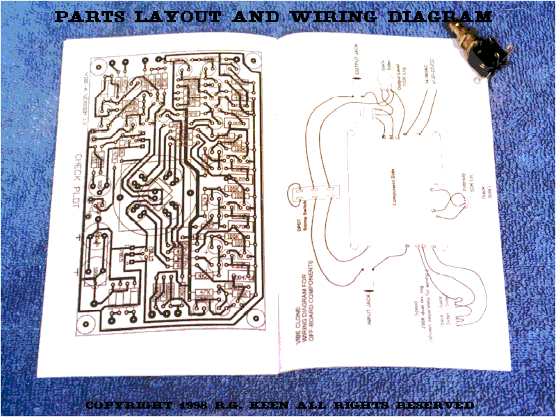
Parts Placement and Check Plot for the board |
This diagram shows where the parts and copper traces go and how to get the right parts in the right places, in the right polarity. Has outlines of the part over a "ghost" diagram of the traces as seen through the board. |
|
Parts list |
Complete list of parts, with supplier part numbers and estimated costs where possible, and in some cases possible substitutions for more readily available or more economical parts. |
|
Schematic |
Complete schematic diagram, including wiring to controls, etc. May include some "modern" options like true bypass where the original did not have such niceties. |
|
Tech notes |
A description of how the circuit works from the electronics viewpoint and how to get the thing made up into a usable effect. |
|
Off board wiring diagram |
Shows how to hook up the wires to the controls, jacks, and switches |
|
Packaging sketch |
A sketch showing how the board, controls, battery, jacks, etc. can fit into the recommended enclosure. |
These layouts are completely new, and many cases are much smaller (and tidier) than the old, often unavailable effects they are an attempt to recreate. They are an attempt to provide a way for you to experiment with making an effect that may be simply unavailable or impossible to find. They are not replacements for effects that may have been reissued. Note that the names of the original effects and the companies that made them are copyrights and/or trademarks of their respective owners, and are used here for reference only. The layouts are NOT exact copies of the old layouts, although the repair versions of certain boards may have been designed to fit exactly in the earlier equipment for repair purposes.