Copyright 1993-2000 R.G. Keen - Geo-Fex Cybernetic Music
This is an introduction to the basic means of distorting a signal in a musically useful way. The approach is as non-technical as possible. I use the simplest signal waveform, a sine wave, to illustrate all these, although a guitar is much more like a sawtooth than a sine wave. The clipped waveforms will be shown in their raw state. Tone controls or filters after the clipping will radically alter the waveshapes.
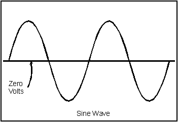
Sine wave. This is the purest tone possible, just a single frequency. No musical instrument does a really pure sine wave, although tuning forks and some flute tones approach this. Notice that the waveform is smoothly rounded everywhere, no sudden changes in direction.

To engineers and mathematicians, the sine wave is the simplest waveform, because any other repetitive waveform can be built up from a collection of sine waves of different frequencies and sizes. Sine waves, on the other hand, are not made up of anything more basic that anyone has found yet.
In music, we recognize the significance of the sine wave by talking about fundamentals and partials. A fundamental is taken to be the basic tone of any given note - for instance the frequency A-440 is the standard for musical tuning. This is a sine wave that has a frequency of 440 Hz (Hz is short for "Hertz", and stands for one cycle per second). We recognize that a tone of A-880 is one octave higher than A-440. Musicians may refer to a musical note that has both A-440 and A-880 mixed as have a fundamental and the first partial. A frequency of three times the basic note frequency is also referred to as the third partial of the basic note. Four times the fundamental is the fourth partial, and so on into the stratosphere.
Engineers call partials "harmonics". When we talk of "total harmonic distortion", we mean whatever is left after taking out the fundamental sine wave in some waveform. All the harmonics, or partials and any noise make this up.
Mild clipping. If we take that same sine wave and electronically clip off the tops and bottoms at some clipping level, we get something like this:
Just snipping off those tips has a big effect on the sound. A pure sine wave is kind of boring sounding. Distorting the sine wave by clipping introduces a whole bunch of partials or harmonics. The sound is much more interesting to listen to, as long as we don't get too carried away with it.
There is a real difference in the sound depending on how sharp the "edges" are where the clipping occurred. Perfect, sharp corner edges cause buzzy, hard edged sounds. Rounded, smooth edges give a smooth sound. While there is no particular reason why these two effects should be related, it does seem to be true that smooth sounds are related to smooth waveforms, and buzzy or harsh sounds are related to sharp corners on waveforms.
Musically, some so-called "overdrive" pedals do something like this. It's just a bit of clipping. While I have shown the positive and negative clipping levels as the same - so-called symmetrical clipping - there is no reason that they must be the same. The human ear can clearly hear the difference between symmetrical and non-symmetrical clipping.
If we want to get really distorted, we can amplify the sine wave a lot, and then clip it off at the same level as we just did the un-amplified sine wave. The amplified sine wave get really, really tall, then is clipped back. It looks like this:
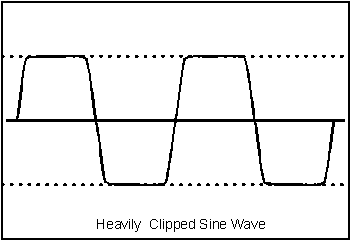 As you can see, the sine wave
has been amplified a lot, then clipped off so that only the starting part of the
sine wave remains. This has even more harmonics than the moderately clipped one.
The result is a heavily buzzy sound.
You can see where this is headed, right? The more we amplify the sine wave and clip the excess back off, the more it approaches a square wave. The next two examples show the completion of this .
There are in fact instruments that are designed to create perfect square waves from sine waves by amplifying the crud out of them and then clipping the result back down to a very small fraction of its amplified size.
REALLLY clipping the sine wave gives a sound that's a high gain, hard edged metal kind of sound. Lots of heavy metal distortion pedals pedals do this then round the corners with some filtering.
You eventually get to a true square wave. Some early fuzzboxes actually did this. It sounds something like a synthesizer; very buzzy. This can sound OK, even useful, unless you hit two notes at once, then makes an unpleasant harsh distortion from the two (intermodulation distortion).
Intermodulation distortion is the bane of fuzzbox technology. If you take any two pure sine waves and intermodulate them, you get not only the two sine waves, but two other frequencies - the sum of the two originals, and the difference. If we had A-440 and A-880, and intermodulated them, we'd get 440, 880, 440 again from the difference, and 1320, which is three times A-440. This would actually sound pretty good.
The bad part about this is that we picked the best possible example. However, if we take A-440 and the note an octave and a third up, 1467 Hz, we get the original notes plus 1026 Hz, and 1907 Hz. These frequencies are NOT related to the original note and sound harsh or out of tune. We're also talking about sine waves. Real world signals always have some harmonics, and we get the sums and difference of all the harmonics, too. Very unmusical.
So the name of the game is to produce harmonic distortion, which makes musically good sounding notes and to minimize intermodulation distortion, which makes un-musical squarks and harsh buzzes. Unfortunately, no matter how hard we try, we can never get all harmonic distortion and no intermodulation distortion. But we can pick between distortion mechanisms to use the better ones and avoid the worse ones.
One way to keep mostly harmonic distortion is to not have sharp corners. "Tube-ish" distortion is much like this.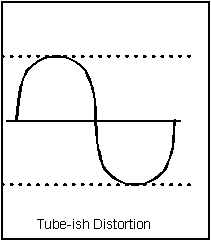 It has very softly rounded,
squashed tops when done on square waves. From the engineer's standpoint,
something very different from the clipping progression above has happened
here.
A true techie thinks of any wiggle of a waveform as carrying information. A pure sine wave is almost devoid of information, having no wiggles or corners in that smoothly rounded top. However, if we took a square wave and massively amplified it, or a triangle wave, or a wave with spikes all over its top and did the same amplify/clip operation on it, we'd get exactly the same result as with the sine wave with massive clipping.
In effect, we can't tell after massive clipping what we originally started with. We've actually lost the information about what the wave used to be - it's forever removed by the clipper. We should not be surprised that all waveforms sound alike after massive clipping. It's kind of the Veg-a-matic of sound.
The compression-limiting clipping that does this tube-ish distortion is very different in the information sense. The top of the wave is compressed, sometimes massively; however, the original information about what the input wave used to be is not lost, just compressed. Distortion with this compression nature keeps some of the flavor of the original input, which many guitar players like.
This is not a perfect replica of vacuum tube distortion. Vacuum tubes are not symmetrical enough to do this. The CMOS gate based pedals like the ElectroHarmonix Hot Tubes can. Tubes are similar, but the tops and bottoms are not mirror images. The sound is soft, smooth onset, touch sensitive, "bluesy".
There are things we can do other than clip or limit a signal.To get an octave sound, we can full wave rectify it.
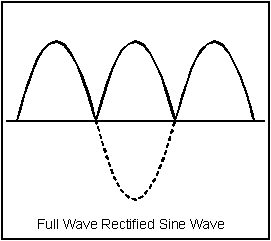
A full wave rectified sine wave just has either all the positive or negative half-cycles inverted. A lot of math is needed, but it eventually tells us that the lowest frequency component in this is twice the original sine frequency - an exact octave higher than the original sine.
This trick has been used to one degree or another in the Tycho Brahe Octavia, UniVox SuperFuzz, Foxx Fuzz-Wah, and Foxx Tone Machine pedals. It is common to follow full wave rectification with diode clipping and some filtering, as the raw waveform sounds a bit buzzy and strange - it literally has information in it we don't want!
Having the signal completely full wave rectified does eliminate the fundamental frequency. Sometimes this is not desirable. If we half wave rectify a sine wave, the result still has a lot of the fundamental in it, but also has a noticeable octave sound. We can also partial full wave rectify a signal, which makes for an even more noticeable octave sound. There is a continuum of sounds between pure sine, partially rectified and full wave rectified, having more octave sound as we go.|
|
|
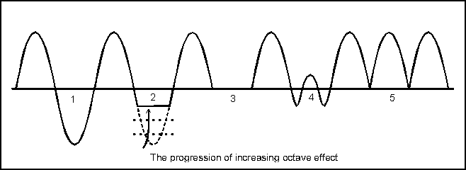
In fact, anything we do to one side of a sine wave but not the other will introduce an octave sound.
The following picture illustrates this. From an undistorted sine wave (1), we progressively clip the negative half cycle (2) until the signal is half wave rectified (3); adding even more second harmonic (4) progresses until full wave rectification (5).
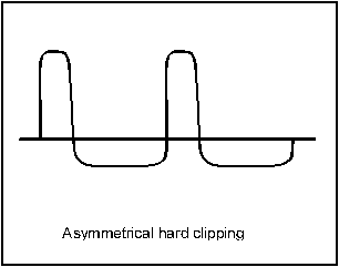
One specialized form of distortion is worth noting. High gain followed by, asymmetrical clipping, hard clip on top, soft compression on bottom turns out to be a good sounding compromize for guitar. The fabled Fuzz Face did this - at least when you got one of the good ones.
And some comments on the circuits that actually produce the distortions:
I tried to catalog all of the ways I could think of that have been or might be used for musically useful distortion, with some running critique.
Two kinds of distortion: As I noted above, simple harmonic distortion, which generates distortion products that are related to the fundamental frequency by low-integer multiples, is universally accepted as adding character to instrument sound. Intermodulation distortion, which produces non-musically related frequencies at multiples of the sum and differences of two frequencies, is considered to sound harsh to the ear. Unfortunately, all known harmonic distortion methods also produce intermodulation distortion when fed two or more different frequencies simultaneously, but the exact method of producing distortion may result in lower or higher amounts of harsh sounding intermodulation; there is no exact way to predict the harshness. In general, the "softer" the clipping or distortion (that is, the fewer and softer the "corners"), the less intermodulation, but this is only a generality.
PRE and POST distortion EQ: Filtering of the signal both before and after the distortion usually has at least as much if not more to do with how the distortion sounds than the actual method of distortion.
A combo amp with a speaker or two and an open back implements a multi-pole lowpass filter all by itself. This is at least one of the reasons that a miked amp is preferable to running a distortion signal directly into a PA mixer. The speaker cabinet's lowpass action smooths off those offending treble shrieks. An electronic multipole lowpass filter is the essence of all those "cabinet simulators" you see.
Filtering BEFORE the distortion is also interesting. Hendrix is reputed to have used a Wah pedal before his Fuzz Face. The bandpass effect makes the signal bigger at the frequencies boosted by the Wah, so those frequencies get distorted most. You get an interesting change in distortion depending on what notes you hit. This cuts a lot of the harsh sounding intermodulation distortion, too. Anderton used this principle in designing his "QuadraFuzz", which split the incoming signal into four frequency bands and distorted each band separately, then mixed them back together. This method gives a much lower intermodulation distortion by avoiding having more than one frequency distorted together.
One of the most interesting experiments with distortion most guitarists ever make is to put a multiband graphic equalizer both in front of and behind a distortion pedal. Some time spent playing with the knobs on this one will give you a whole new outlook on distortion.
Duty Cycle: Based on an article in Electrical Engineering Times, continuously changes in the relative amounts of clipping between the positive and negative halves of the signal may be an important factor in distortion sound. This article (by Brian Murphy, interviewing John Murphy, who used to be chief engineer at Carvin; EET, October 3, 1994) outlines Murphy's ideas on the degree to which he can simulate tube distortion in solid state designs. He holds that if you filter properly, soft clip, and arrange for the duty cycle of the clipped signal to vary with varying signal levels, you get something very close to tube distortion. This is the basis of the "tube emulation" circuitry in Carvin's SX series of amps.
Silicon is reputed to clip abruptly, causing a harsh sound. Germanium clips at about half the voltage of a silicon diode, but is reputed to turn on more slowly in its smaller range. LEDs turn on at about two silicon diode drops, and are also reputed to be slower turn on, with it and germanium giving more "tube like" sounds. Some units with "tube" in the title use LEDs or germanium for clipping.
Oddly enough, the Marshall JCM800 uses a set of two pairs of silicon diodes back to back as clippers. This seems strange in a Marshall, but it is there. When I looked at the schematic, I first thought it was a protective clamp for a tube grid, but the circuit doesn't work that way. They are there for the distortion.
I've never seen a schematic with zener clipping for music, but they are used in the signal processing world.
One recent entry is the diode-connected MOSFET transistor. This connection makes for a "diode" that has about a two volt forward drop, but a "knee" that is very softly curved.
The most famous example I can think of of the diodes-in-the-feedback-loop pedal is the Ibanez TS-9 Tube Screamer. Almost every commercial pedal manufacturer has made one of these. The quality of the sound seems to depend heavily on the overload and recovery characteristics of the opamp and the pre-and post- clipping filtering. For more info on the Tube Screamer pedal, see "The Technology of the Tube Screamer".
The Octavia pedal and the the old Foxx Tone Machine (as well as the "new" Experience pedal, which is almost exactly the same circuit as the Foxx) use a form of full wave rectification followed by diode clippers and filtering. The clipping and filtering seem to tame the odd buzziness of the raw rectification.