Sing-Wah - A Vocal-Emulation Wah Circuit
Copyright 2001 R.G. Keen. All rights reserved.
No permission for local copies or serving from pages other than http://www.geofex.com.
Hot-stuff, grabber intro:
Looking for a unique wah sound? This one ought to do it! The
point of using a wah in most cases is that it has a vocal quality about the
sound it produces. As I noted in another article, the voice quality comes from
the fact that human speech is made by shaping the mouth and throat so that there
are several resonances or "formants" in the frequency response of the
vocal tract. A wah sounds a bit voicy because it's a resonance that moves
around; however, it's not a real vowel sound because there's only one resonance.
Semi-technical intro to the theory:
Real voice simulation requires two or three formants. Simulation
work early last century came up with voice emulators that could produce
recognizable speech by simulating the voice resonances this way. This wah uses
the same techniques.
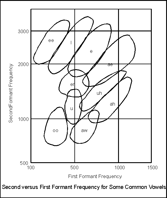
To do a more voice-y wah, we have to look at what the resonances
should be, and how they relate to one another. The figure illustrates this
point.
 The
frequency of the first two formants (resonances) F1 and F2 need to not only be
certain values, but also have certain relationships between them to be
recognizable as vowel sounds. This figure shows a "map" of the
frequencies and relationships of the two. In general, if you make a filter with
a lower formant F1 and a higher formant F2 in the dead middle of one of the
labeled vowel regions, any harmonic-rich sound piped through the filter will
sound like that corresponding vowel.
This is not as discrete as the figure makes it look, by the
way. Vowel sounds that
people make are a continuum. If you put your formant frequencies on the edges
between two vowel sounds, it will sound like a vowel sound halfway between the
two. This also happens in human speech, and accounts for some of the features of
speech we hear as regional accents. In the center of one of the regions, the
sound is pretty clearly the intended one. At the edge between two regions, it's
a halfway between vowel sound.
As an example, if we have an F2 (high) resonance at 2500Hz, we
will get a vowel sound that goes from "ee" to "i" to "eh"
to "ae" as we shift the F1 (lower) resonance from 300 to 400 to 700 to
1100 Hz. If the shift between F1 frequencies is smooth, there will be a smooth
shift between these vowels. If it is abrupt, there will be sudden transitions
between them. Smooth transitions will sound more human-like, because we can only
move our mouths and throats in smooth movements, not instantaneously.
Although you can get some voice qualities by using one fixed and
one moving formant, to really get a wide variation of vowel sounds you need to
move both resonances. This will make for a much more believable set of voice
sounds.
Down-to-brass-tacks build-it stuff:
So, to make a good voicey-wah, we need two filters, and we need
to move them around. This is a *very* open ended kind of requirement, and could
be done dozens of ways. I initially intended to use either an existing inductor
based wah, a twin-tee wah, or a multiple-feedback wah circuit (see The Technology of Wah Pedals)
for both formants and merely sweep the wah by changing the control resistance.
This turned out to be an OK, but not terribly good choice for reasons we'll see
more later.
The frequencies of the formants are pretty simple to pick out;
you can read them off the chart above. I picked the following frequencies,
largely because they're almost in the center of the vowel regions:
| |
F1 |
F2 |
| ee |
300 |
2700 |
| i |
400 |
2500 |
| e |
600 |
2300 |
| ae |
800 |
2000 |
| ah |
800 |
1200 |
| aw |
600 |
800 |
| u |
500 |
1100 |
| oo |
350 |
800 |
| uh |
750 |
1400 |
| er |
500 |
1600 |
|
As you can see, the regions are pretty wide.
This is a real help because we don't have to get terribly precise about
hitting an exact frequency with the filters. Also, there are several
with pretty much the same frequencies. This helps us with the
practicalities of implementation.
As I mentioned earlier, I had to pick a wah circuit. I simulated the twin-tee
wah, the multiple feedback wah, and the inductor style wah to use with variable
controller resistances. I was not happy with the simulation results of
these. They all had trouble with the range of frequencies that are needed.
From lowest to highest, there is about a three to one frequency range in each of
F1 and F2. That was hard to do and get good responses from the filters.
|
Instead, I picked out an old favorite of mine, the graphic-EQ style filter.
See Simple, Easy Parametric and Graphic EQ's, Plus Peaks and Notches
for more info on the background of this one.
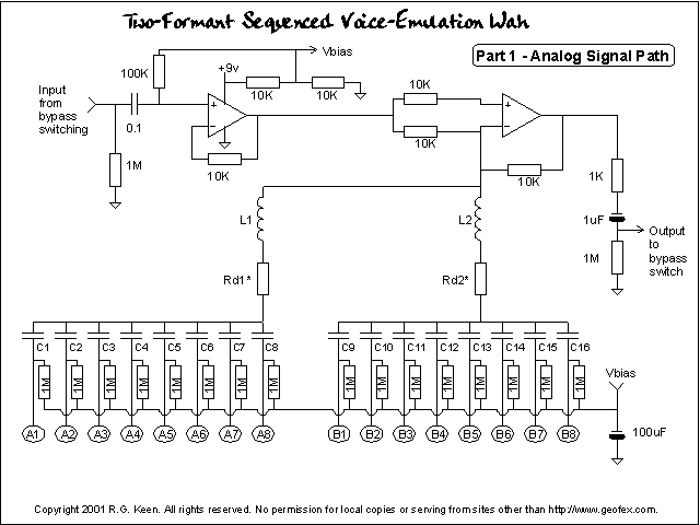
 This
circuit is the full-blown setup - assuming I didn't make any typos drawing it
up, which is always a possibility. The opamp on the left is a buffer; the one on
the right does all the heavy lifting. It's set up so that if you left off the
stuff below L1 and L2, it would have a gain of 1. The L1 and L2 circuits are the
frequency selective stuff that makes for the filter notches.
In essence, the inductor-resistor-capacitor (only one capacitor is used at a
time) combination acts like a low impedance at one frequency. This cuts the
amount of negative feedback the opamp gets at that one frequency and so the
response peaks. Two networks introduce two peaks.
For L1 and L2, I used the Radio Shack 1K to 8 ohm transformer primary
mentioned in The Technology of Wah Pedals. This is about a half-henry, and is
cheap and easy to find.
Rd1 and Rd2 are damping resistors. All by itself, the inductor/capcitor
series filter is very sharp, highly resonant. By adjusting the series resistance
we can tame this resonance down and broaden it. These will be an adjust-to-taste
item.
Capacitors C1-C8 make up the set of frequency determining caps for F1 while C9-C16
determine the frequencies for F2. The string of 1M resistors connecting to Vbias
keep the DC level on each capacitor constant so that there's not a pop when the
capcitors are switched.
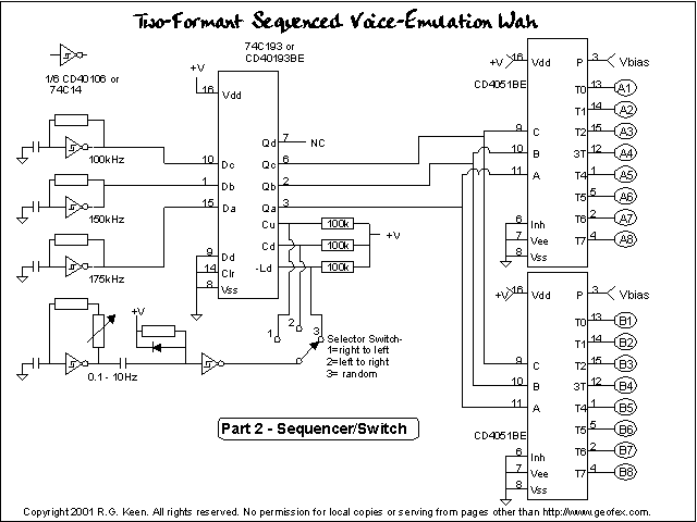
 The switching circuit is what puts the Gee-Whiz in. I used a variation of the
Up/Down/Random Wah Sequencer that I designed
earlier. The only adaptation was that I added a second CD4051 switch in parallel
with the first, and arranged both to switch one of eight capacitors to Vbias.
This is the switching arrangement and sequencer. The switching has been reversed
to allow for capacitors - the caps are attached to the throws of the switch and
the pole is connected to Vbias, which is at AC ground.
The switch inputs and outputs are all at Vbias DC level. This keeps any
switch pop down to as small a level as possible.
Note that the sequencer provides both counting up, down and a random
selection of states for the F1 and F2 frequencies.
So - how do we arrange the capacitor values?
The sequencer is going to set both 1P8T switches (that's what the CD4051's
do) to position 1, or 2, or ... 8 at the same time. To pick a vowel that we want
to hear, we take setting 1, corresponding to selection A1 and B1, and pick
capacitors C1 and C8 to be the values that set the frequency we want.
Then we pick setting 2, and pick C2 and C9 to be another vowel. We keep
going until we have eight vowels we want selected. These become the values of
capacitors we wire in for C1-C16.
The capacitor values are simple. Capacitance C for any position is C= 1/
(2*pi*f)(2*pi*f)L where L is 0.5H. C comes out in uF. We just pick the nearest
standard value, because the frequencies don't have to be exactly on.
| |
F1 |
F1 Cap (uF) |
F2 |
F2 Cap (uF) |
| ee |
300 |
0.56 |
2700 |
0.007 |
| i |
400 |
0.32 |
2500 |
0.0081 |
| e |
600 |
0.14 |
2300 |
0.0095 |
| ae |
800 |
0.079 |
2000 |
0.0012 |
| ah |
800 |
0.079 |
1200 |
0.035 |
| aw |
600 |
0.014 |
800 |
0.079 |
| u |
500 |
0.02 |
1100 |
0.042 |
| oo |
350 |
0.41 |
800 |
0.079 |
| uh |
750 |
0.09 |
1400 |
0.025 |
| er |
500 |
0.02 |
1600 |
0.002 |
|
Pesky Cap Values... ugh! As you
might guess, practicality is going to rear its ugly head somewhere, and
this is one place it does. With L1 and L2 fixed at about 0.5H (and who knows exactly
what they measure!) the capacitor values are not likely to come out on
standard values. And sure enough, they don't. In fact, it's worse
because in the bigger 0.1 to 0.5uF range, it's hard to find a
commercially available capacitor even in "standard values" at
all. Usually you only get 0.1, maybe 0.22 or 0.33, and 0.47 uF.
What this all means is that you're going to have to make some
compromises. What we'd all like to do is to just bang in the required
value in a nice polyester/Mylar capacitor. That won't happen unless you
have better resources for caps than I do, because most distributors just
don't carry them. In poring over the Mouser catalog, I came to some
conclusions.
|
First, you're almost certainly going to have to parallel one, two or three capacitors that you
can get to make up something close to the right value, especially for
those four biggest F1 capacitors of 0.14, 0.32, 0.41 and 0.56 uF. Second, unless
you have a big box to put this in, you may not even be able to fit polyester
caps in at all. They're big. 'Course, you can just choose to use a big box for
it, so it could be made to work.
Even with paralleling, it's not likely that the formant frequencies you
actually get are going to be exactly the frequencies you wanted. There are two
main reasons. First, the capacitors in the larger sizes are usually +/- 20%
tolerance. On top of that, the inductance of the inductor you use will have a
tolerance as
well. The easy, cheap way is to use the Radio Shack transformer's primary
inductance I mentioned in The Technology of Wah Pedals. However, this thing does
not have a specified, guaranteed primary inductance value; the ones I've
measured just happen to work. It's likely that the inductance will vary by +/-
25% on these. So you can see that the center frequencies of the filters you end
up with may not be exactly where you thought they would be. The wide latitude on
the ranges of formant frequencies helps us; we picked frequencies in the center
of the regions, so maybe the result will still be in the intended vowel region.
If not, you can trim the capacitance for an intended formant until it does sound
right.
I made some compromises on the PCB layouts. I decided that getting this into
a 1590B box is a worthwhile goal, so I settled for laying the PCB out for axial
ceramic capacitors. These are much physically smaller than polyester, and even
better can be stood on end like resistors. There are 36 capacitors in there and
16 resistors in just the frequency selection components. To get it to fit, I
decided to use two boards, one with the logic and CD4051 switch chips on
it, and one with the signal stuff on it. The boards are exactly the same size
and shape and have mounting holes at exactly the same place. This lets you mount
the logic board right next to the box and space the analog board above it on
spacers on the same mounting screws. With some luck (I haven't measured the RS
transformers yet) this stack will be less than the height of a 1590B, and the
two will both fit inside it. Well, as they say, no guts no glory. We'll see.
I'll add the PCB layouts in the next installment.
There are other ways to do this, of course. One could use only one capacitor,
but connect it to AC ground with a pulse-modulated waveform at a very high rate.
This would make the capacitor's value appear to vary. That's a whole different
kettle of fish, though. Another approach to switching from frequency to
frequency is to use the 1:8 decoder (CD4051) to drive LED's instead of switching
signal. The LED's then drive LDR's to turn on the various capacitors. That
approach will not have the sensitivity to switching noise that the 4051 does,
but it will be both expensive (16 NSL-32's!) and may not give you a good enough
Q, as even switching LDR's have minimum resistances in the 100's of ohms.
More work needed on that one. You can also put a unique Q resistor in series
with each capacitor if you find that you want different Q's on different
frequencies.
 The
frequency of the first two formants (resonances) F1 and F2 need to not only be
certain values, but also have certain relationships between them to be
recognizable as vowel sounds. This figure shows a "map" of the
frequencies and relationships of the two. In general, if you make a filter with
a lower formant F1 and a higher formant F2 in the dead middle of one of the
labeled vowel regions, any harmonic-rich sound piped through the filter will
sound like that corresponding vowel.
 This
circuit is the full-blown setup - assuming I didn't make any typos drawing it
up, which is always a possibility. The opamp on the left is a buffer; the one on
the right does all the heavy lifting. It's set up so that if you left off the
stuff below L1 and L2, it would have a gain of 1. The L1 and L2 circuits are the
frequency selective stuff that makes for the filter notches.
  The switching circuit is what puts the Gee-Whiz in. I used a variation of the