Version 1.7 9/27/99 - More wah circuits, how and why the classic wah works, and some mods, plus connections to human voice info
Copyright 1999 R.G. Keen all rights reserved. No permission for local copies or posting from web sites other than http://www.geofex.com/.
The stock "wah" pedal has been around since at least the early 60's. While there is a persistent rumor that an early version of a wah mechanism was found in the wreckage at the Roswell crash site, I can categorically state that the government says that this is nonsense, and that no such thing happened. It was only a weather balloon. Made of ... uh... magnesium... and uh... nylon, which was top secret then. That's my story and I'm sticking to it.
In any case, this thing produces a distinctive tone that is well loved by the expressive guitarist. The history is a bit obscure, but it probably came about as a follow on embellishment of the first Vox mid range booster effects. The nasal tone of the MRB became a vowel-like "aaaahh" with the arrival of a way to sweep the center of the effect.
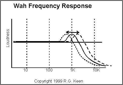
What a wah does is clear - it is either a bandpass filter or an overcoupled lowpass filter that exhibits a resonant peak just at its lowpass rolloff frequency. The resonant peak can be moved up and down in frequency by the player, and this makes for a striking emulation of the human voice making a "waaaah" tone, or its tonal inverse, "aaaooow". There are several means to this end, and the circuits are well understood for the classical implementations of such filters with opamps, state variable filters and the like. In a future update of this article, I'll go through that in some detail. If you're curious about why a wah sounds a bit like a human voice, and maybe why it doesn't sound -more- like a human voice, see "Human Voices and the Wah Pedal".
There are several kinds of wah circuits That have been used through the years. The original was the Vox style inductor based wah circuit, followed by others, most notably the twin-T circuit, the multiple feedback opamp active filter circuit, and most elaborate of all, the "state variable" style circuit used in the Mutron 3. Everyone's favorite still seems to be the inductor based Vox style, although the others have their supporters. You'll find more information on the twin-T circuit, the multiple feedback circuit, and the state variable circuit in this article as well.
The Vox circuit is pretty simple, only a couple of transisors and an inductor. The really pertinent question that had puzzled many people - including especially me - is how do you get a moving resonant frequency out of a fixed inductor and a fixed capacitor? How does that silly two-transistor wah circuit get a moving bandpass out of a circuit that changes neither the inductor value or the capacitor, but only what amounts to a volume pot?
It took me a while, but the trick is - the wah pot, the second transistor and the fixed capacitor implement an electronically variable capacitor. The inductor is and remains fixed, and the capacitor is electronically varied and so the circuit has a variable tuning LC filter to cause the effect.
To get down to how this works we'll disassemble a two-transistor wah of the classic Vox style and learn how everything in there works, and have a good time with the circuits on the way.
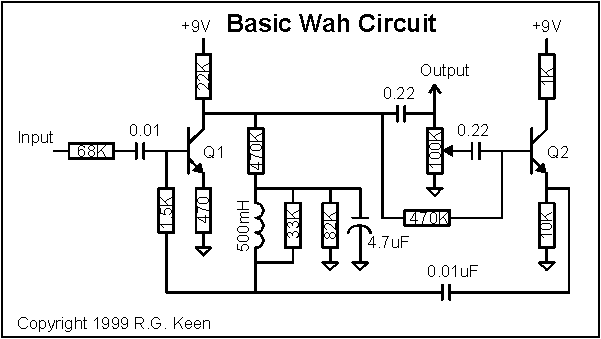
Let's dive right in. The first transistor is a straightforward feedback amplifier. Ignore for the moment the parts separated by the dotted lines. These are separated from the first transistor by capacitors, and so cannot participate in DC biasing. The transistor is biased into linear amplification by the voltage on its own collector which feeds current to the 470K resistor, some of which is shunted to ground by the 82K resistor. The rest of the current through the 470K goes to the base through the inductor and the 33K resistor which parallels it and the 1500 ohm resistor leading to the base. The inductor's DC resistance is quite low compared to any of the other resistors (typically 40-75 ohms), so the base current is determined primarily by the 470K and 82K resistors and the 1500 ohm resistor. In fact, the 1500 ohm resistor is small compared to the 470K resistor, so we'll ignore it for a moment; we can ignore the inductor, 33K resistor and 1.5K resistor. This is one form of the classical voltage feedback biasing arrangement, and the values are chosen to give a reasonable linear range of swing on the collector.
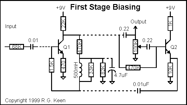
If we just guess that the collector is sitting at 4.5V, that gives a collector current of about 200uA, an emitter voltage of about 0.1V, and a voltage at the base of 0.6V roughly. The voltage across the 470K is then 4.5V - 0.6V or 3.9V, and the current through it is about 8uA. If the gain of the transistor is around 200, then Ib is 1uA, and the voltage across the 82K resistor is 0.6V for a current of about 7uA. Hah! An approximate match!
The biasing seems to work for high gain transistors at least. We could re-refine the estimate, but for our purposes of understanding the operation, it's enough to be able to be sure that the transistor is in its linear region, and not going to be clipping for small signals at least. In fact, measurements on real circuits show the collector of Q1 normally sits between 3.0V and 5.0V, so the guesses we made were OK, if a bit rough and ready.
In terms of gain, the gain of just the transistor itself, from base to collector is about equal to the load resistor divided by the effective emitter resistor. This is the 470 ohm external emitter resistor plus the internal base emitter junction resistance, about 25mV/Ic or about 125 ohms. So the small signal voltage gain of the transistor is about 22K/595 = 36. On the other hand, we have that input resistor we ignored that will drop some signal. The input voltage is divided down by the voltage divider composed of the 68K input resistor and the effective transistor input impedance. The input impedance is that same 595 ohms times the (ill defined) Hfe which we guessed at 200, or about 119K. The input voltage is divided by 119K/(68K + 119K) or about 0.636. So the overall stage gain is 0.636*36 or about 22, give or take some. Once again, we can't know this exactly because it involves the transistor gain, but we can get a good enough ballpark number to understand the operation.
Leaving aside the first stage for a moment, let's look at the second transistor. The second transistor is biased into the linear region by a 470K resistor from the collector of the first transistor, and if its Hfe is high, the voltage at the base will be only slightly smaller than Q1's collector voltage. The base current needed to bias Q2 is only the current to cause its emitter to pull a 10K resistor up to about 4.5V. This is (4.5V/10K) divided by the Hfe of the transistor, or about 2.25uA. The voltage dropped across the 470K is then about 470K*2.2uA=1.1V. The base of Q2 should sit about 3.4V - not quite as high as we had guessed, but we now know it will be greater than this voltage and less than 4.5V, which is close enough for our purposes. Q2 is a linear emitter follower, and small signals will not run it into saturation or cutoff.
Nota Bene - I did go measure a real Wah pedal's voltages. The collector voltage on Q1 was actually 4.14V and the base voltage on Q2 was actually 3.64V . Not bad for some back of the envelope scratching, huh?
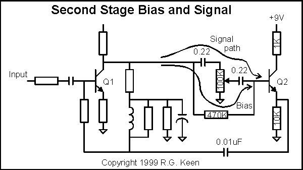
This emitter follower buffers the signal from the wiper of the wah pot, which is simply a volume-control-style voltage divider to ground. The emitter of the transistor connects through a 0.01uF capacitor to the junction of the inductor and the 1.5K resistor to the base of Q1. How the devil do you get a moveable frequency resonance out of that?
The secret is this. The inductor looks to the second transistor like its far side is grounded, through the 4.7uF capacitor. To the inductor, the capacitor kind of looks like it's grounded because its far side is connected to the emitter of Q2. Q2's emitter has a low output impedance and therefore looks like "ground" if you ignore the signal coming out of the emitter. At the junction of the inductor, capacitor, and 1.5K resistor, the voltage looks like the voltage that would happen across a parallel L/C circuit. However - the current through the capacitor is NOT determined by the voltage across the inductor/capacitor, it is also determined by the voltage driving its "ground" side, and that voltage is increased or decreased by the position of the wah pot. If the wah pot setting increases, the capacitor will let more signal current through because the voltage driving it at Q2's emitter is bigger, so the capacitor has to let in more signal current. If the wah pot setting decreases, the capacitor will let in less signal current. A "capacitor" may be thought of as a special instance of ohm's law by the amount of signal current it lets through. The change in the effective current through the capacitor makes the capacitor look bigger to the inductor and rest of the circuit than it really is! We have a variable capacitor!
That's why the frequency of resonance changes. The capacitor looks bigger than it really is for resonance purposes, and the amount it looks bigger is controlled by the wah pot. The first transistor is a block of gain to give you an active resonance, the wah pot and second transistor modulate the effective capacitance in a resonant circuit composed of the inductor and the variable capacitor.
As another way of looking at it, the capacitor is being fed by a buffered replica of the signal from the collector of Q1 and is fed back to the base of Q1, so it looks and acts like a Miller Effect capacitor. The difference between this and a real Miller effect capacitor is that the wah pot has the ability to vary the amount of signal that drives the capacitor. Since the Miller Effect multiplies the actual value of a feedback capacitor by the gain of the stage, the wah pot can vary the apparent value of the capacitor from its normal value up to Q1's voltage gain times the actual value.
Because of the way the feedback is connected, the actual overall response is that of a lowpass filter with a resonant peak, the peak being the LC peak. In the stock circuit, the gain through the circuit is overall slightly less than one, peaks at resonance, and falls off above the resonance.
There are more implications of this than are immediately apparent, as well as some exciting effects that can be made from it.
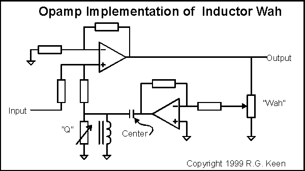
It turns out that except for the subtle distortions they generate, there isn't any magic about the transistors. You can use opamps to do the same job. They won't give you the subtle tone shadings of a vintage transistor wah pedal, but the wah will work the same way.
Although opamps are not the be-all of the signal world, they simplify some things. In particular, the basic wah circuit can be made to do some outstanding tricks with an opamp implementation - more flexibility, more controls, Vox-style inductor saturation, multiple wahs, and much more - coming in the next installments.
There's a legend in the music world that the sound of the old, original Vox Wahs with "Fasel" inductors is superior to what can be had from modern wahs. It turns out that there is some fact behind this legend. While it's clear that the other parts in a Vox Wah have something to do with the tone, the inductors have long been the subject of speculation. The wahs with Clyde McCoy's picture on the bottom plate and inductors marked "Fasel" are especially prized. I have a longstanding mistrust of any legendary mystical goodness that is not explainable by technical analysis, so I always wanted to test the magic inductor.
I was entrusted with one of the magic versions by a friend, and spent some time in an EE lab with this wah and a garden variety Crybaby. I took both inductors out and measured their inductance, resistance, self-capacitance, and came to no good conclusions on why there should be any difference in the sound. It wasn't until I put a sine wave generator through the inductor and looked at the current through the inductor on a spectrum analyzer that the differences showed up.
I saw no differences at first with tiny sine wave drives. It wasn't until I turned the generator up that differences appeared. The Crybaby inductor performed exactly as I would have expected it to. That is, it had an output that was essentially a pure sine wave right up until the sine was big enough or lowe enough in frequency to start it into the first touches of saturation. When that started, I got precisely what theory predicts: appearance of the third harmonic of the dirve waveform, followed by fifth, and finally a touch of seventh when I really pushed it. However, when I did the same to the Fasel inductor, the onset of saturation-generated harmonics happened a bit sooner, and a second harmonic appeared with the third! As I turned the drive up, the fourth rose with the fifth, and I never got a seventh harmonic. The inductor, all by itself was clipping asymmetrically.
I queried some older and wiser EE's who have spent a career on magnetics. We came to the conclusion that the only way this could happen was if the inductor core had some kind of magnetic offset in it, so one polarity of the waveform saturated earlier than the other. However, none of them had ever seen this in a signal inductor like the ones I was testing. The only good explanation was that the inductor core itself was carrying a magnetic offset, a whiff of permanent magnetism. This was mildly astonishing because that is something that linear ferrite cores are explicitly designed NOT to do.
The best explanation I could come up with is this. The inductor in the classic wah setups carries the DC bias current for the first transistor. While this is only microamps, long exposure to this unidirectional bias could result in a remanent magnetization of the inductor core if the core material was not very good in the classical, linear EE sense. It's possible that Vox merely specified the circuit, the maker (Jen, I think, in Italy) made the early wahs from as inexpensive a material as they could, and the slight deviation from linearity resulted in a sound that the folks at Vox liked. That is - it was a happy accident resulting from being cheap. I've never heard another explanation that accounts for the differences. There are differences, and measurable ones, and ones that square with reasonable explanations for how the thing works and sounds. This legend's true.
I have not seen or heard any of the supposed "next generation" Fasel style inductors, so I can't say whether they are true to the originals.
One thing that became obvious is that you could artificially get a more linear core material to have an offset, and in the easiest way. If we're always pumping current through the inductor, we can get any offset we like by just pumping more. If we were to put a second winding on a wah inductor, we could force DC through it from a current source circuit, which would force the "center" of the magnetic operation toward one or the other saturation points. Of course, this is not possible with a pre-wound and potted wah inductor, but is emminently feasible if you happen to wind your own. It's even more feasible if the inductor you use happens to have a second winding, like the Radio Shack transformer that is mentioned later. This secondary can just be hooked up and current fed through it. I intend to do this as as soon as I get some bench time. Note that I've been saying "current source". You can't just use a resistor, because transformer action would reflect this resistance into the inductance winding as a load and damp the resonant action of the inductor. The minimum you need is a transistor connected as a current source to keep from doing this.
The potentiometer (pot) that gets rotated to make the wah do its thing is also a source of myth and legend. While the original Italian Vox pots were almost certainly off-the-shelf things, they were obtained at a time before the MBA's convinced everyone to keep far fewer things on the shelves than they do today. As a result, "off the shelf" might well have had a far richer meaning than it does today. The questions surrounding the pot are (a) what value of pot resistance do you use and (b) what taper is the resistance in the pot?
As to value, the earliest wahs are supposed to have used 470K, 500K or 1M pots here. All modern pots use 100K. There is still more work to do to find out how this affects tone.
Taper is a big item. It's pretty certain that the pot taper in commercial pedals is not linear. An audio taper comes close, but wah afficionados say that it's not quite right. The best candidate seems to be a semi-logarithmic taper (like audio, but not as extreme) or a semi-log taper. Part of the search for perfect taper is a result of the fact that the full mechanical travel of the wah rocker pedal will not turn a normal potentiomenter through its full 300 degrees of mechanical rotation, so there is some pot travel that remains that is not used because the rocker can't turn it far enough.
The Teese Wah Pot is reputed to have "dead zones" at each end of it's travel, possibly a linear taper between the extremes. The Fulltone pot is also reputed to have a modified taper. Whether the HotPot, Rock Potz, and others have standard tapers or not is not well known.
Now that we know that the pot is doing, we can do some things about making special tapers for pots. More on those later.
"Tropical fish" caps are named for their multicolored outer surface. Don't know the material. The other parts make so much difference that I would recommend using current production Mylar or polypro and twiddling all the rest of the stuff before counting on the cap material to be a big deal. There may be something here - I'll do more digging.
The basic wah circuit itself can be modded to do a number of things that might be useful. To determine what to change to get what effect, I threw the circuit into my circuit simulator and looked at what happened to the responses. Using the following schematic, we'll look at what happens. In the schematic I have "genericized" the naming of the parts so we can talk about them by something other than their values.
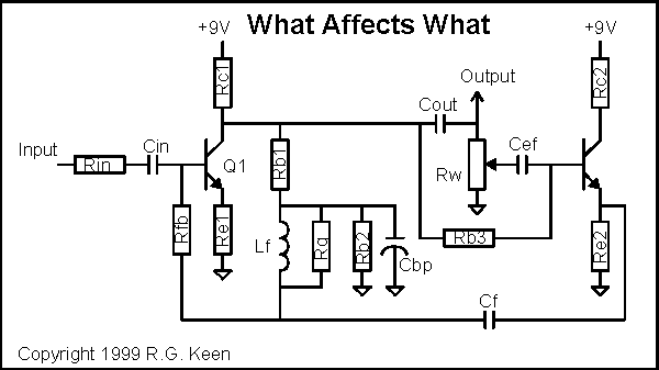
From our earlier tear-down report, we know that Q1 is a voltage gain amplifier, and that Q2 is an emitter follower that just buffers the signal voltage from the wiper of the Wah pot, Rw. We know that the inductor is fairly passive, and only participates by setting the L side of the LC filtering. Let's take a look at every part, with some comments on what the parts do and what happens when they change.
|
Part |
What it does |
|
Q1 |
Voltage gain transistor. Open loop voltage gain is partly determined by this. Has some effect on the overall sound. Its distortion, if any, contributes to the tone of the pedal. There is some tone change to be had by substituting for this transistor as a result. This is the one to substitute if you can only find one "5117" transistor. |
|
Q2 |
Emitter follower transistor. Very little effect on tone as long as the Hfe is large enough. Gains of 200 or greater will all sound pretty much the same. |
|
Rin |
Affects the overall signal level out. Lowering this will increase the output signal level. Somewhere between 33K and 47K gives you unity apparent gain with true bypass switching. However, lowering it also lowers the input impedance and therefore increases tone sucking if you don't either use true bypass or buffering at the input. |
|
Rfb |
-- still working this one -- |
|
Rc1 |
Directly affects biasing point and gain of Q1. Open loop gain goes up as this goes up, and at the same time, the bias point on Q1's collector goes down, moving it closer to saturation. May affect tone if it moves Q1 into a nonlinear region for part of the signal. Large values (47K to 100K) will almost certainly cause distortion. |
|
Re1 |
Directly affects biasing point and gain of Q1. Open loop gain goes up as this resistance goes down, and at the same time, the bias point on Q1's collector goes down, moving it closer to saturation. May affect tone if it moves Q1 into a nonlinear region for part of the signal. Small values (0 to 200 ohms) may make good changes to the wah's tone by moving the transistor into a soft saturation region of its biasing. The wah range also moves down as Re1's value decreases. |
|
Rb1 |
Primary bias resistor for Q1. This resistor largely determines the operating point for Q1. As it increases, the voltage at Q1's collector goes up and vice versa. No effect on Q1 gain as long as it's reasonably big because of the AC bypassing effect of Cbp. |
|
Rb2 |
Secondary bias resistor for Q1. This resistor is the second major determinant of the bias point for Q1. As it goes up, the collector of Q2 goes down, closer to saturation. No effect on Q1 gain because of the AC bypassing effect of Cbp. |
|
Rb3 |
Main biasing resistor for Q2. The value of this resistor is not very critical as long as it (a) is not so small that it offers a significant amount of signal leakage around Rw and (b) it is not so big that the tiny base current of Q2 drops a lot of voltage and lowers the DC voltage at Q2's emitter and causes distortion. Probably anything between 220K and 2.2M works, although I haven't checked those values closely. |
|
Rq |
This resistor is the primary determiner of the Q, or sharpness of the bandpass/resonance effect of the filter Values lower than 33K make the filter less sharp, reducing the quality of the wah effect. Values up to 100K contribute to sharper, peakier, more resonant tones. If it gets too sharp, the wah effect can be lost because it may not hit harmonics to emphasize. |
|
Rc2 |
Provides noise isolation for Q2. Can probably be omitted with some degradation in noise, or maybe no ill effects at all. |
|
Re2 |
Not too critical. Probably OK between 4.7K and 18K. Not much effect on tone unless Q2 is biased into an area where it clips. |
|
Cin |
making it bigger can allow more lows in and add fatness. If you want this, change it to about 0.1uF to 0.22uF. |
|
Cbp |
Important that it be large enough to bypass all signal at its (+) terminal to ground. From 4.7uF on up, little effect on sound. As it gets smaller, the sound becomes more of a loudness variation and less of a wah. If this cap is defective, wah pedals sound like volume pedals. |
|
Cout |
-- still working this one -- |
|
Cef |
-- still working this one -- |
|
Cf |
Primary determiner of the center frequency of the wah effect. Changing its value moves the whole wah sweep range. Bigger values move it down towards bass, smaller values move it up. |
|
Lf |
The inductor. Just make sure it's in the range of 400mH to 600mH, then tune with Cf.; "magic" inductors have properties all their own, and can add a sweet tone by virtue of their saturation charactersistics |
|
Rw |
Sweeps the Wah. Usually 100K. The exact value may not be too important as long as Rb3 and the gain of Q2 are large enough. Can be modified with tapering resistors to get a specific sweep, and the sweep can be narrowed by putting fixed resistors in series with the outside ends of it. Usually people want the opposite, a sweep across more of the range in a smaller foot pedal travel. |
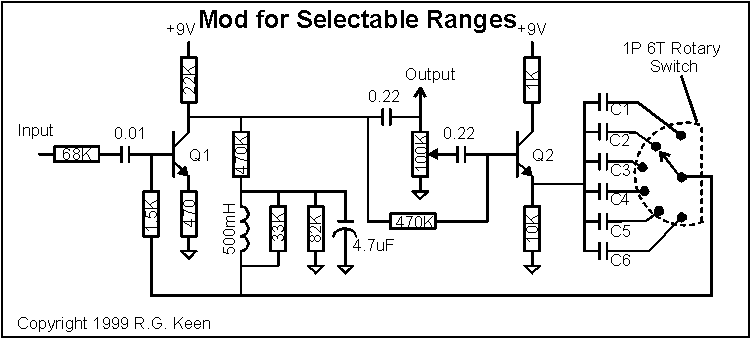
Install a switch to select between different values of Cf. Smaller values move the sweep range up, bigger values move the sweep range down. You can use any kind of switch. A SPDT will give you two choices, a 1P6T switch as shown will give you six choices.
Add caps in parallel with the inductor
better to switch the Cf value
Vary Re1 up or down
A popular mod is to temporarily replace Re1 (stock value 470 ohms) with a 1K linear pot. As the resistance is decreased through the original value towards zero, the sound starts getting richer, as a consequence of the first transistor's gain going up. The increase in gain is accompanied by a modest increase in distortion, accounting for the fatness. When the resistance gets near zero ohms the wah will be at or near self resonance, and will self oscillate at the low end of its range, then wah into notes as you rock forward on the pedal. Touchy, but cool! As the resistance of the pot increases above the nominal value the sound starts to get less "wah-ey" as the gain of the first stage drops and the feedback can't make as peaky a resonance. You can either find a value you like and put in a fixed resistor with that value, or mount a pot somewhere you can twiddle it.
Change the Rq to change the "sharpness" of the bandpass.
If you change the value of Rq, the nominally 33K resistor parallel to the inductor, you change the sharpness of the resonance. Larger value resistors narrow the resonance band. Smaller values damp the resonance more and spread out the resonance band but make it less peaky, so the effect thins out. Some people swear by values like 51K as being incredibly good.
This trick will let you either cure a scratchy pot (which is what Anderton originally proposed it for) or put the rocker pedal arbitrarily far away from the wah circuit. To do that, just remove the circuit board from the inside of the wah, being very careful to note what connects to what so you can undo this if you want. Neat diagrams help! Then make up a cable with shield and two wires in it. One supplies +9V to the top of the pot, the other carries the wiper voltage back to wherever the wah circuit physically resides. The shield carries ground. I did this with a Vox Reissue, and it worked great. There is still this little problem of how do you bypass it then, but I have to save some secrets.
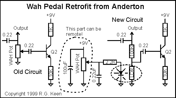
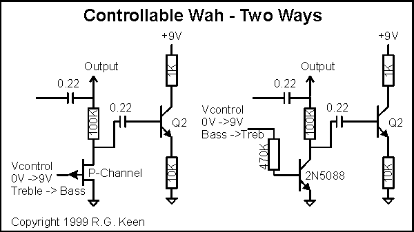
Here are two ways to make a voltage controllable wah. In both cases, the actual circuit relies on a transistor to take the place of the LDR in Anderton's wah retrofit. The first uses a P-channel JFET, which is on (low resistance) when its gate and source are at DC ground, and goes progressively higher resistance as the gate is taken more positive than the source.
The second way uses the collector-emitter resistance of an NPN transistor in the same way the LDR was used. In this case the resistance is highest when the control voltage is low, and gets lower as the control voltage feeds a trickle of current into the base of the NPN.
Both of these suffer from distortion as the signal level gets high. The LDR has no such problem.
Tone Sucking (loss of treble in the bypassed position)
The bypass switching in wahs up through the mid 90's used an SPDT switch. The switch does not provide for true bypass switching, so the input of the effect is connected to the input jack at all times. This means that the wah pedal input loads down the guitar signal, and worse, loads it more at treble frequencies than at bass frequencies. The sound gets duller and less lively. There are two cures, and they work about equally well. First, you can put in a DPDT true bypass switch. Second, you can add a buffer in front of the wah to keep it from loading down the guitar signal. There is an article on how to build the buffer onto the internal wah printed circuit board at GEO.
Pot wear
With all the rocking back and forth that a wah pot gets, it gets more wear than any panel mounted control ever does. The mechanical slider that moves over the resistor element inside literally wears some of the material loose. This material can collect in ways that can cause the slider to lose contact with the resistor material, and when that happens, it makes a "scrackle" sound as the pot is rotated. There are two cures: either (a) clean the pot or (b) replace the pot.
Cleaning the pot should be regarded as a stopgap measure. It will help for a while. Go to a Radio Shack or an electonics supply house and get a spray can of "tuner cleaner" or "electronic contact cleaner". Spray this into the pot while rotating the pot shaft. The scratchiness should be much better. Opinions vary as to whether you should buy tuner cleaner with a lubricant in it and/or lubricate the pot after cleaning it. Geoffrey Teese has advised people to spray inWD-40 after using tuner cleaner on the theory that the cleaner dries out the factory applied lubricant and WD-40 is a reasonable replacement. There are tuner cleaners that say they leave a lubricant on the surfaces.
Some people swear that any lubricant will accelerate the deterioration of the pot. The right thing to do is to consider cleaning as a temporary measure and replace the pot.
Replacement pots are available from several sources. Analog Mike, Fulltone, and Mojo sell a heavy duty 100K 2W pot for about $30. Dunlop sells the "ECB24 Hot Potz" which comes pre-assembled with nylon gear, nut and washer and is available in quantity from New Sensor Corp for $20.25 in a $100 minimum order. Analog Mike and Mojo both sell the Teese Roc Pot. Geoffrey Teese custom builds these pots to original taper of the original Vox Clyde McCoy pots. Fulltone sells a similar pot. In any case, count on spending $15 to $30 to keep your wah wahing. Some people think the replacements sound better than the originals.
I suppose since I've already put the schematic in, I should mention that you can use Craig Anderton's LED/LDR trick from his GP column to fix a scratchy pot. The schematic has already been shown under "Mods". This replaces the wah pot with a fixed resistor and LDR, and uses the original pot only to change the current on the LED. It works, and it's very smooth indeed. The original pot will then last until it develops completely open spots.
Loss of signal level
After putting in a true bypass switch, people often find that they lose a bit of volume when the wah is kicked in. This comes from one of two places; either the forward gain of the wah circuit is a bit below one, or the loading of the wah circuit cuts the guitar signal down a bit. You can correct for this by lowering the value of the 68K input resistor somewhat (to 33K-47K maybe) to increase the gain. Notice that this also lowers the input impedance and may change the tone of the wah in the effect setting. The bypass setting will be unaffected because of the true bypass switching.
No "wah" sound, only volume change
Cbp is failing. Replace it with a new 4.7uF to 22uF aluminum electrolytic capacitor.
No "wah" sound, only treble change
Inductor Lf is probably open. Get a replacement.
"Wah" range noticeably decreased when certain effects used AFTER the wah.
The input impedance of the effect is loading down the output of the wah, as the input impedance of the next effect appears effectively in parallel with the collector resistor of Q1. This directly cuts the gain, which we've seen is responsible for the variable-capacitance effect that gives the wah its variable-frequency sound. The solution is pretty simple - buffer either the input of the following effect or the output of the wah.
Let me start this with advice - don't do this, at least not the classic foot operated rocker pedal. It's not because the electronics are hard. They're not, they're almost trivial. You don't even have to come up with any super special parts, excepting the inductor, which we'll cover.
Rather, it's because making a reliable foot-rocker pedal to turn a pot is HARD. If you're a good machinist or tinkerer and also play a guitar, OK, go for it. Otherwise, buy a dead Crybaby and refurbish it. The rocker pedal mechanics is not something to attempt lightly if you don't have the tools to do the metal work. I often find repair shops have a pile of dead Crybaby shells in various states of cannibalization that they will part with fairly cheaply. You should consider making the whole mechanical setup only if you have no other good options.
The electronics isn't too hard. Perfboard works well, and PCB's aren't too difficult to make for this one. I recommend getting your mechanical packaging settled first, then making sure that the board you're going to build it on fits in side the mechanical packaging properly. Do this before putting parts on the board.
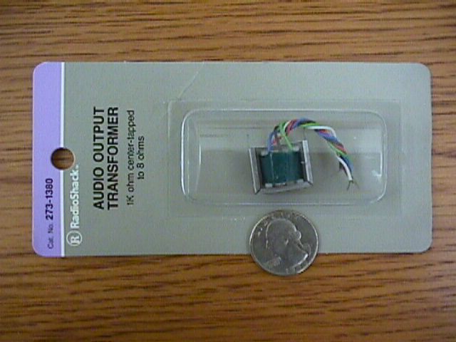
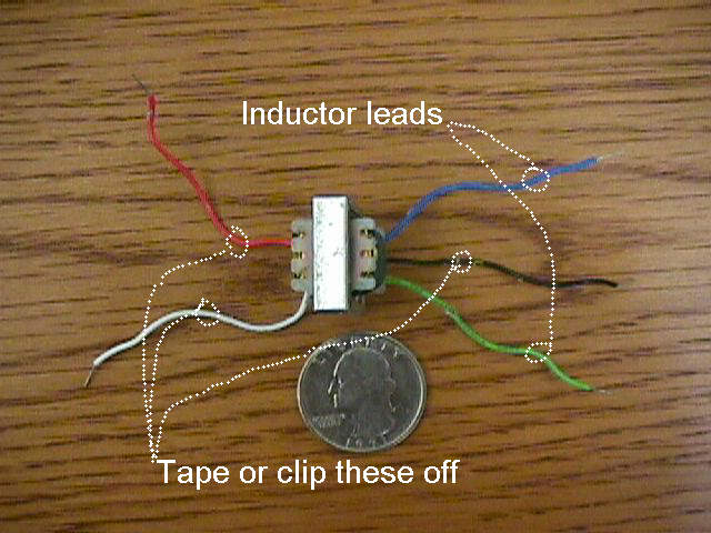
Beyond mechanical packaging of the pot rotation setup, the critical issue for wah builders is finding a 500mH inductor. There are several ways:
Here are some pictures of the easiest solution, the Radio Shack transformer.
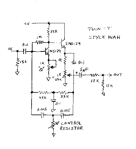
A much less mysterious circuit is the twin-T style wah. The naming of the twin-T is reasonably obvious from looking at the circuit. There is one "T" composed of two resistors in series and a capacitor to ground. The second T is made of two capacitors in series with a resistor to ground. The T's are hooked in parallel. They're not exactly twins, but close enough for naming. The twin T network all by itself is a notch filter. As a sidelight, it's about the only circuit composed of only resistors and caps that can have an infinitely deep notch - that is, if you tune the values of the R's and C's perfectly, the frequency at the notch of the filter will be completely removed. Most applications don't need this perfect tuning, and in particular wahs don't. To get a bandpass (humped) response, we use the twin-T network as negative feedback around an amplifier. The Twin T passes all frequencies outside its notch, but attenuates the frequencies near its notch. Since this is negative feedback, the frequencies we pass through most easily reduce the gain most, and the frequencies that are not passed through the feedback network are not reduced by feedback, so they have a great deal of gain. The negative feedback connection therefore inverts a frequency notch to a frequency hump, which is exactly what we need for a wah.
This circuit is taken from the 1970 Popular Electronics article "The Waa-waa" by Simonton. I've deleted the switching so we can see how it operates. The first transistor is a high gain amplifier, with the actual gain settable by the 1K "Q" trimmer. The second transistor buffers the collector of the first so that output loading will not affect the gain. The twin T is clearly discernable. The control resistor is just a variable resistor to ground.
Multiple Feedback Opamp Circuits
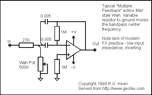
Another bandpass filter that can be wah-ed back and forth with a variable resistor is the multiple-feedback active filter. These things use RC networks around opamps to simulate the second order response of an LC network. As you can seen in the simplified schematic, once again only one variable resistor to ground can vary the center frequency of the bandpass over the useful range of frequencies for wah pedals.
Both of these circuits are what I call resistor-to-ground wahs - their center frequency varies with only a single variable resistor to ground. This is much simpler to automate electronically than the inductor style wah, where the wah frequency is controlled by a three terminal voltage divider. The disadvantage of these two circuits is that they don't have the subtle distortions that the inductor circuit does, and so they don't have as interesting a tone - on their own at least. As usual, that merely means that they have other uses for which they're best suited.
Messing around with Wahs - What can we do?
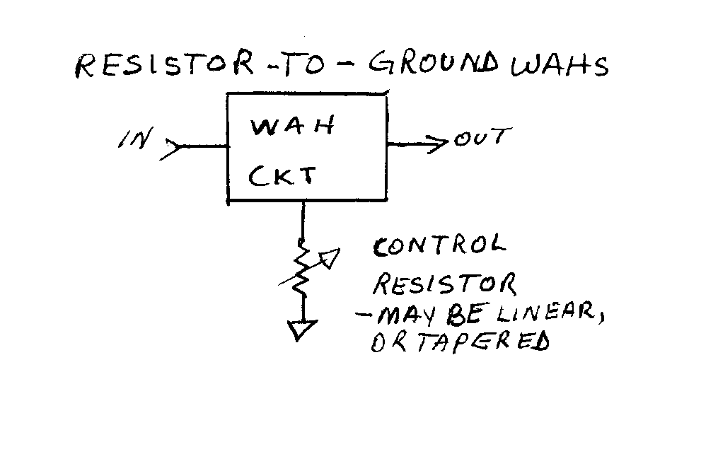
The resistor-to-ground wah circuit gives us a simple way to mess with the center frequency. Anything that makes for a variable resistor to ground will make them wah, so we can play tricks. The resistor can be any style - an LED/LDR module, a JFET, a diode string, even the collector-emitter resistance of a bipolar transistor, as well as a plain old pot.
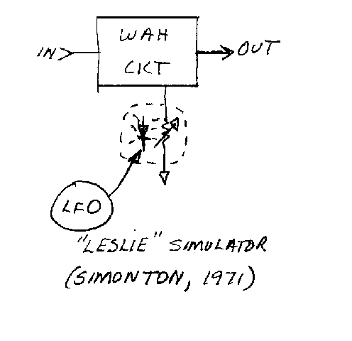
One of the simplest things we can do is to just drive the variable resistor with a Low Frequency Oscillator (LFO) like this:
This was another application that was published by Simonton and originally used the Twin T circuit, but it works equally well for the multiple feedback circuit or the inductor wah as converted to resistor-to-ground, as we'll see later. Although this is not a very good simulation of a real leslie cabinet, it does have its own unique tone, and is a lot of fun. It has a tone reminiscent of the organ in a county-fair merry-go-round.
You can also convert this into an auto wah by just deriving the control voltage from the loudness of the incoming signal, and using that to modify the center frequency.
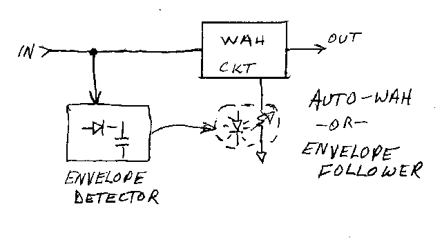
This very arrangement is the essence of several commercial pedals. The prototypical one is the Dr.Q follower from EH.
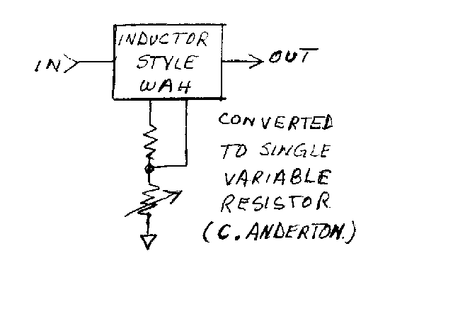
And here's how to convert the inductor style wah to a single variable resistor to ground.
There's no law that says only one wah at a time sounds good. In fact, it will sound more like human speech if we use two. Let's look at some ways to do that.
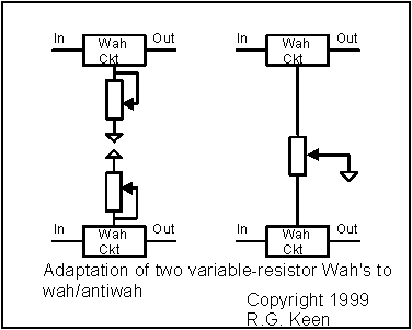
With two resistor-to-ground wahs, we can make an adaptation that uses a single pot to move both of the frequencies around in opposite directions at the same time
To do the same thing with inductor style wahs, we can either first convert them to the single-resistor-to-ground circuit first, or we can use a dual pot. This is a pain because we'd have to get a log/antilog pot. Tapering resistor as noted in "The Secret Life of Pots" come to the rescue, as we can make a dual log/antilog pot from a dual linear one.
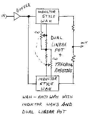
Notice that in this sketch, I've shown the input buffer to prevent tone sucking by the input loading, and a resistive mixer to mix the two outputs that was not shown in the first wah/antiwah sketch.
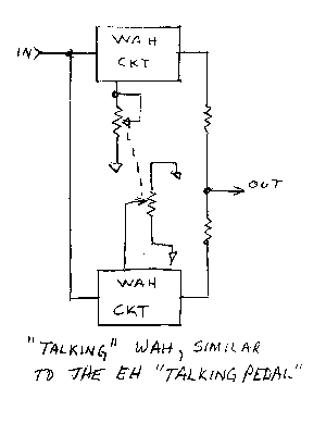
As noted in the blurb on human speech and formants, for some really interesting vocal effects, we'd like to have the two wahs move not just opposite one another. We can do this with another pot trick. If we have a wah that only needs a variable resistance to ground, nothing says how we have to use the end lugs. We can ground both of them if we like. That means that the resistance from the wiper to ground is maximum in the center of the pot's rotation, and gets smaller whenever we turn it away from center in either direction. The wah's center frequency will be lowest in the middle, get higher toward either end.
If we combine a stock wah with a wah set up for center-lowest by using a dual linear pot, we can get a much more vocal quality. EH did much the same thing in the "Talking Pedal". It used two multiple feedback wahs in this circuit. The exception was that it used a special dual pot where one section had a tap near the center of the pot rotation that was grounded. The wiper then was closest to ground in the center, but had the highest resistance to ground at either end. It's possible to disassemble a pot and paint on a tap with conductive paint if you're desperate - see"The Secret Life of Pots".
R.G.