 ?
?Copyright 2000 R.G. Keen. All rights reserved. No permission for local copies or serving from web sites other than http://www.geofex.com.
[Point to Point] [Stripboard] [Pros and Cons] [Capacitances] [PCB Right] [PCB Wrong] [Good Stripboard] [Bad Stripboard] [Myths]
Ever hear this one?
"Get a point-to-point wired amp - those PCB amps are no good. They just don't have the tone they did in the old days."
The deeper you dig into this issue, the more repair techs you'll find that say that PCB amps are no good. They'll give explanations involving things like tiny traces run too close together, and the capacitance leaking signal from place to place and then make the leap that this somehow spoils the tone of the amp. Is this bit of folk wisdom right?
Yes and no. The short version of the answer is this:
There is no technical reason that PCB amps *can't* be every bit as good as
point-to-point wired amps - or stripboard wired amps, which is what the grizzled
techs usually refer to. However, there are some serious reliability (not tone!)
shortcomings in most of the PCB based amps that have been put on the market;
this is the origin of this folk myth.
At the bottom of both sides of this question is self-interest. On the side of the amp makers, most of the time the PCB conversion is done as part of a cost saving measure; the same motive to change to PCB's also drives changing to cheaper practices and parts all around. This most often gives worse tone. They're doing less than the best they could, for money.
On the amp tech side, PCB amps that have been done poorly have frequent breakdowns. They are not as easy to repair as hand-soldered terminal wiring. They require some delicacy in fixing, and they can be a true pain to get the boards in and out. So to the techs, they break more often, and are fiddlier to repair. The techs usually can't charge more for PCB amps, so - no surprise - they don't like them much.
So - PCB based amps, from what we've seen so far, have poorer reliability and techs don't like to repair them; but that is because they were poorly designed from a reliability standpoint in the first place. The tone is not necessarily poorer. Here are some comparisons
| Advantages | Disadvantages | |
| True Point to Point | Approaches "ideal" in electronic terms; lowest parasitic coupling
and crosstalk if done well.
Sturdy. Withstands repair surgery well. |
Very expensive to design well
Very expensive to produce in today's market Usually heavy. |
| Stripboard | Less expensive to make than PTP.
Parasitics and crosstalk OK for most applications. Parasitics and crosstalk are variable depending on lead dress. Withstands repair surgery well. |
Higher parasitics than PTP.
Variable parasitics. Moderately expensive to produce in today's market |
| PCB | Inexpensive to downright cheap to produce Absolutely fixed, known parasitics - whether good or bad Extremely reproducible. |
Needs special planning and design to avoid mechanical
problems.
Repairs must be done delicately if it needs repaired. |
Most PCB amps that have been produced *have* been poorer than tube amps, for reasons having nothing to do with the PCB's. Like plastic bobbins in transformers, this does nothing to change the tone. The *other* poor practices that go with a cost-cutting attitude that were introduced at the same time may, but PCB's are unfairly indicted.
If you're interested, here's some more information about the differences in point to point, stripboard, and PCB construction practices that DO make a difference.
Point to Point (PTP) - What is it and what's good
about it ?
?
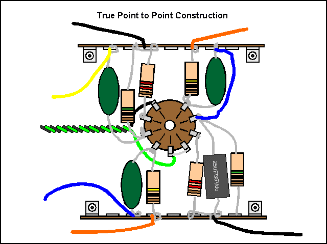
This is one version of real "point to point" construction.
The view is from underneath the chassis surface, looking at the bottom of a 9 pin miniature tube socket and two terminal strips that the circuit is built on. Good point to point layout makes the actual component bodies bridge most of the distance from the socket lugs to any other connections. Really, really good PTP construction will have the components arranged in almost a star pattern, all of them leading radially away from the socket.
What's important there is that (a) all the component leads are pretty close to being as short as they can be (b) the component to component wiring lengths are as short as possible (c) neither the components nor the wires criss-cross one another (d) the lengths of paralleled wires are about as small as they can be.
The reason that all these are important is that there is an unavoidable bit of capacitance between any two electrical conductors that are at different voltages. You can think of this as a little "ghost" capacitor between every combination of two points on the schematic - ugly! These ghost capacitors are often referred to as parasitic capacitors.
This capacitance is proportional to the facing areas of the two conductors, and inversely proportional to the distance between them. For maximum coupling between two conductors. they need to be as close together as possible, and have the maximum area exposed to one another.
For two wires, the closest they can get is with their insulation touching. For the maximum area, they'd have long parallel runs; for minimum area, they'd cross at right angles. In true PTP, the components and wires are as far from one another as it's practical to get, and where crossovers are needed, they can be at almost right angles. Also, the wiring between amplifier sections can be minimized by laying out the tube sockets in a manner that the signal flows directly from one tube circuit to the next with no long runs of parallel wires. Also, the terminals themselves space the wires a goodly distance away from the presumably grounded metallic chassis.
The worst case for cross coupling in wiring of any kind is where the wires run parallel and with their insulation touching. I spend part of a Saturday morning digging through my collection of electronics and physics texts to come up with some rules of thumb for how big the capacitive coupling is. Of course, this varies all over the map depending on the layout and wire sizes. However, for two 22 gauge hookup wires with kind of nominal insulation thicknesses, the capacitance between the two wires is about 0.381pF per inch. Ten inches of parallel run, the capacitance is 3.81pF. With the wires crossing, there's only about 0.025" of wire "parallel", so the capacitance is on the order of 0.008pF.
Oddly enough, the capacitance of two PCB traces under similar conditions is actually less. For two 0.025" wide traces spaced a conservative 0.075" apart, the capacitance is 0.317pF per inch. Finer traces even closer together do have a higher capacitance per unit length, but much less than you'd expect - it goes up much less than linearly with smaller, finer traces. We have the curious result that wires and PCB traces have very similar parasitic capacitances, and PCB traces have a slight edge over wires. That kind of means that it's how you use them, not which you use, huh?
Note that a poor PTP layout can be a nightmare of criss-crossing parts and wires that can loose a herd of electronic demons. What makes a PTP wired circuit good is (a) careful planning and (b) very skilled labor doing the wiring neatly and carefully. For reason (b), true PTP is very expensive, and has been even as far back as the late 50's.
True PTP construction is good for frequencies up to UHF (several hundred MHz!!) if properly done. This is the reason all that old tube radio equipment was laid out that way. Good PTP layout has wires that almost never come close to one another, and when they do, the cross instead of running parallel. That's good, but it's a long way from audio to UHF, so maybe there's something else that can fill the bill.
The kind of construction in amps that is most often referred to as "point to point" is not really point to point at all. Most amps use some kind of insulating board with either eyelets (notably Fender) or turrets set into the board, and the components strung in neat little rows on the board.
All the connections to tube sockets are made with wires from the stripboard to the tube sockets and controls. Note that unlike true PTP, the wiring lengths from the components to the tube sockets are no longer as short as they were. Also, the wires are often stranded wire, and free to move around, where the component leads in PTP were solid, and pretty much held in place by being short and stiff. To get easier wiring, we have sacrificed the very short interconnections that are a characteristic of good PTP wiring.
The freer, stranded wires can now move around relative to one another. This means that they have variable capacitances among them! The coupling of signal from place to place by accident (if it was on purpose, we'd use a wire or capacitor) is now a variable that depends on how you push the wires around after they're installed. The placement of wires in this kind of construction is referred to as lead dress. Not too surprisingly, poor lead dress can cause the wrong signal to get picked up and amplified. This can cause hum if the wires get too close or too parallel to those green/black filament heater wires, or oscillation if an output signal wire gets too near a sensitive input.
Good stripboard construction can approach the performance of true PTP. However, stripboard construction abandons the electronic elegance of true PTP for easier, faster manufacturing by less-skilled (and cheaper!) workers. With stripboard, assuming a minimum of good workmanship on putting the parts on the stripboard, the differences in quality will depend primarily on the wires that lead away from the stripboard to the outboard controls and other components.
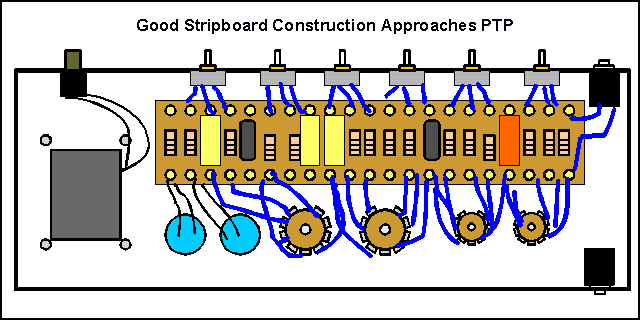 This is an illustration of a
good style of stripboard layout. The input and power transformers are at
opposite ends of the chassis. The tube sockets, stripboard, and controls are
laid out so that the wires from the stripboard to the sockets and controls are
as short and direct as possible - no long runs of parallel wires.
Doing this is not all that easy. It takes a good deal of foresight and skill at the processes of wiring and building things in this style to get the wires as short and direct as possible.
There is also a built-in service problem with this style. Notice that the stripboard is "tied down" by the wires coming off both sides of the stripboard to tube sockets on one side and controls on the other. To lift the stripboard itself requires unsoldering all the wires from one or the other side. Fortunately, most of the parts are easy to get to and replace from the top side if the board has NO components or wires running under the board. Sadly, this is not always true. Poor layout is not limited to PCB's.
Stripboard has a dark side, too. Consider the following picture.
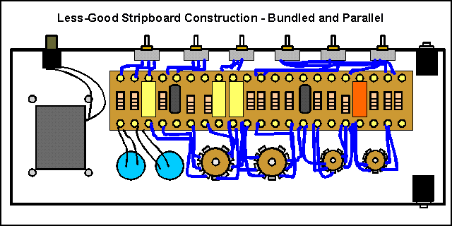 In an attempt to be neat and
tidy, the wires have been gathered into neat, tidy bundles where the wires from
some mechanical area are gathered into a paralleled bunch, often tied into the
parallel bundles by lacing ties (beeswax impregnated cotton is the old
standard!) or nylon cable ties. The advantage here is that you can drive nails
into a dummy amp baseboard at the corners of the wiring, to pre-cut and lace in
place all the wires before ever putting them in an amp. What's wrong with this picture?
That ugly word - parallel. This is how you maximize coupling, remember. Putting the wrong components side by side can cause performance problems in high impedance circuits. Putting the wrong wire in the wrong bundle can make this construction oscillate uncontrollably, or can introduce treble loss. Conversely, not every signal wire coupling makes a difference to every other wire, so there's usually some bundling arrangement that can make this arrangement work OK. Sometimes a signal wire must be shielded to run in a bundle without unwanted coupling.
Which brings up an interesting point - shielding. Shielding a signal wire is most commonly taken to mean running a coaxial wire with the signal on the central conductor and the shield connected to ground. The shield does in fact keep any other signals out side the shield from touching the central conductor by shunting those signals to ground. However, it does it by completely enclosing the signal wire in an enveloping parallel (ack! there's that word again!) sheath. As you might expect from the earlier comments on parallel wires, a wire with a shield completely surrounding it has a lot of capacitance to the shield. Indeed, coaxial cable often has specifications on the capacitance per length of cable. Good cables can be down in the range of 10-15pF per foot. Bad cables can be significantly more. Put a couple of feet of bad shielding cable on a grid signal, and you're losing treble. Better than oscillating, but not perfect by any means.
Wiring capacitances - how much matters?
It's easy to calculate how much is too much for audio purposes. There are two important cases - a capacitor in parallel with a resistor and a capacitor in series with a resistor. We don't consider inductors and capacitors because
Fortunately, we can calculate the frequency where the capacitor and resistor interact the most very easily. This is the frequency where the capacitor's impedance equals the resistance, or F = 1/ (2*pi*RC). To a first approximation we can consider every frequency below this to be unaffected by the resistor, and above it to be unaffected by the resistor.
Guitar amps are a special case of audio amplifiers. Hifi amps have to handle 20kHz, and some purists would insist that 40kHz is a minimum. However, the best wound guitar pickups pretty much cut off above 7kHz and our speakers don't put out much above 4kHz. Even for fuzz-box generated hash, there's not much happening above 10kHz. To make some sense of the huge numbers of variables, we'll have to make some assumptions. The capacitances we calculate may be wrong by a factor of two either way, but then calculating capacitances between free-swinging wires is prone to some error anyway. We'll at least be close enough to know where to dig deeper if we need to.
For a resistor, the "significant capacitance" is C = 1/ (2*pi*Rf), or at 10kHz, C= (15.9/R) uF. If the resistor in question is a 1M resistor, the capacitance will be C = 15.9pF. So a resistor between 8 and 32pF makes a "significant difference" to a 1M resistance. We can see then that the higher the impedances involved, the smaller the capacitance that makes a difference to tone. Likewise, the lower the resistance, the bigger the capacitance must be to make a difference.
One "resistance" we don't see listed on schematics also has a big effect - the equivalent plate resistance. Since we already know that the higher the resistance, the smaller the capacitance that has an effect, we'll consider two high-end examples - the 12AX7 plate and a small-signal pentode plate resistance. The 12AX7 has a plate resistance of about 60K under the conditions it's most often used in preamps. This resistance is effectively in parallel with the plate resistor, so the parallel combination makes for a resistance of about 37.5K in the very common instance of a 100K plate resistor.
We can quickly see then that the wire coming from a 12AX7 plate may have a 37.5K source resistance - that is, it can supply current exactly like a perfect voltage source with a 37.5K resistor in series with it. This wire couples the signal it carries to every conductor anywhere near it - and is loaded by every conductor near it through the parasitic capacitances. If the wire is run right along the chassis, insulation actually touching, this is just like a capacitor to ground connected to the wire. If that capacitance is more than 424pF, then we lose treble above 10kHz, and the amp starts to sound a little dull. We've lost some high-end tone.
If there are 10Vac of signal on that plate wire (not at all unusual), and it runs near a wire connected to an input tube's grid, Then to couple in a feedback signal equal to a typical guitar signal of 100mv, we only need a capacitor of C=15.9/100M uF = 0.159pF - YIKES!! A SIXTH OF A PICOFARAD!!!! We suddenly see how oscillations start - a grid wire too close to a plate wire and a bit of bad luck on the phasing and the amps starts screaming at 100kHz.
OK. So now we know what we're playing with. A fraction of a pF can give us oscillations, but we need something between 8 and 400pF to start cutting treble off, depending on the circuit.
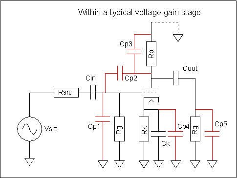 Here's some detailed
considerations on the implications:
The picture shows a somewhat representative tube amplifier voltage gain circuit. The "real" circuit is shown in black, and the parasitic capacitances are shown in red. The excess capacitors may come from wires or PCB traces, doesn't matter which.
Cp1 shunts signal away from the grid when its impedance is less than Rsrc. Cp3 shunts amplified signal around the plate resistor Rp, and Cp2 leaks inverted and amplified signal from the plate to the grid. Every single one of these results in treble loss. Cp2 is the worst because its real value is "amplified" by the voltage gain of the stage. It can be modeled by another capacitor in parallel with Cp1 of Cp2*voltage gain.
So how much capacitance matters?
Cp1 and Cp2: for a representative Rsrc of 35K (typical of a 12AX7 plate with a 100K plate resistor), when the sum of Cp1 and Cp2 times the voltage gain is Cep=1/(2*pi*35K*20kHz) = 227pF, this "dulling capacitor" is eating half the signal. If we assume that all of this is from Cp2, and a voltage gain of 30 for the stage, then the max capacitance we can stand for Cp2 is 7.5pf. As we know from the calculations above, either PCB land or #22 wires are both about .3 to 0.4pF/inch, so we can stand a maximum of about 18 inches of absolutely parallel run wires before we start getting treble loss even at 20kHz. That's a lot! Even when we correct for our assumption that Cp1 and Cp3 didn't matter, allowing for a fifth of the capacitance to be in them, we would be safe with 12-15 inches of parallel, side by side signal run. While the laced-and-bundled stripboard techniques might do this, it's unlikely to be a real problem. Good stripboard and good PCB construction will not even come close.
On Rp, Cp3 could be C= 1/(2*pi*100K*20kHz) or C=79.5pF before we'd get treble loss at 20kHz. That's 227 inches of paralleled wire.
For Rk, there can be no effect if Ck is part of the circuit. Cp4 is completely swamped by Ck. If there is no Ck, the gain of this stage will start rising at the frequency F=1/(2*pi*Rk*Cp4), or for ballpark values, F=1/ (2*pi*1500*7pF) = 15.1MHz!! The tube itself will be cutting off at that frequency. So wiring capacitance from this source has no effect on the frequency response of this tube.
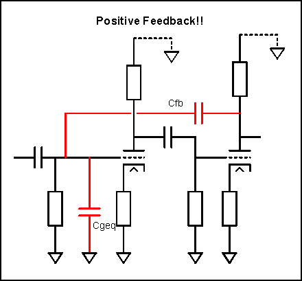 Between two stages the
picture changes a bit. This illustration shows two stages, one following the
other, but connected with a feedback capacitor that we'll assume was caused by
bad wiring. The signal at the second plate is in phase with the signal at the
first grid, and considerably larger. If each stage has a gain of 30, the second
signal is 30*30= 900 times as big as the input signal. For a 0.1V signal, we'd
see 90Vac of signal on the second plate if it was not otherwise limited.
The feedback through the parasitic Cfb is limited by the plate resistance of the second triode, maybe the 37.5K of a 12AX7, and is divided down by the other capacitances at the grid of the first triode, Cgeq, and by any loading at the input other than the grid leak resistor. Let's take worst case, the input open.
Unless we've done something special to make Cgeq smaller, it's probably on the order of 2-3pF. Let's see what Cfb makes the loop gain one, so this thing oscillates. We'd have to have a feedback loss of 900 to make this true, so the impedance of the parallel combination of Rgrid and Cgeq have to equal 1/900th of Cfb's impedance. At frequencies below F=1/(2*pi*1M*3pf) = 53kHz, the impedance is dominated by Rg, and decreases above that. Phase shift also accumulates above that, so let's take the resistance as the limiting resistance. To get oscillation, the impedance of Cfb has to be no more than 900 times Rg, so Cfb=1/(2*pi*900M*10kHz) = 0.018pF. ACK!! 18 FEMTO-FARADS???? HOW DOES THIS THING EVER WORK AT ALL??
It works at all because that picture does not show the whole story, of course; it's too simplistic. There are other parasitics that are not shown in this picture that actually raise the needed coupling well above the 18 fF level. The phase shifts and leakages we've blithely ignored, as well as the parasitics from the first tube itself enter into it as well. However, the math complexity goes right through the roof, so it gets to being a poor illustration, lost in the complexity.
It makes a great morality play for keeping your input and output wires well separated though, doesn't it?
This is actually one of the places that PCB construction would be a big help. The Cfb path would likely be much nearer other signal traces and especially ground traces, which would eat a lot of the feedback signal.
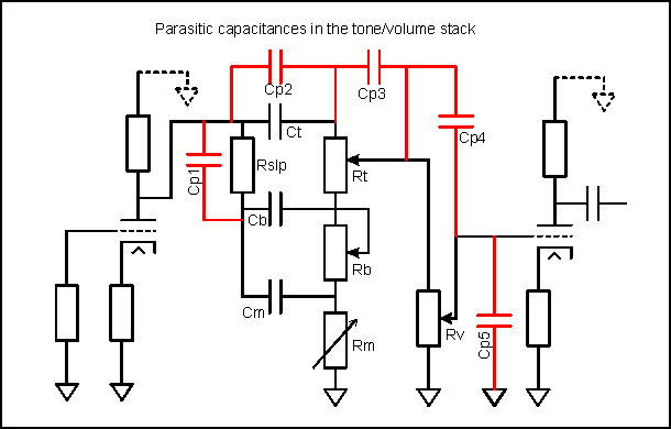 Parasitic
capacitance effects on the tone stack
--- coming ---
How to do PCB construction wrong
This is easy. Just use the technology in ways that ignore the mix of strong points and failings that every technology has. Some examples of WRONG techniques:
Unfortunately, PCB technologies are most cost efficient when everything is connected to the PCB, which encompasses all the things you can do wrong. So you get a clear conflict between cost efficiency (that is, the manufacturer making money) and long term reliability.
How to do PCB construction right
Don't let the boards flex
Don't let the boards get too hot
Don't use solder as a mounting glue
Don't treat high impedance analog signals the same way you do low-impedance digital signals.
PTP Wire Amp Myths You'll Hear
PCB's use traces to connect components that add a small degree of capacitance between the parts which changes the tone/sound
It is correct that PCB's use thin copper traces to connect parts and that there
is capacitance between all the traces. However, the implication that point to point wiring does NOT have such parasitic elements is
completely false. Point to point wiring uses "wires" to connect components; these "wires" also add a small
degree of capacitance between the parts. In fact, for
some instances, hookup wire can have MORE wire-to-wire capacitance per unit
length than PCB traces. There are no wires that *don't* have self inductance, capacitance,
resistance and all the other ills that every electronic part is heir to. Which has more? It depends... you have to know
the mechanical specification of exactly where every part is in relation to every wire and the chassis to compute the
capacitance for either traces or wires. A well designed PCB with attention paid to where the traces go may have bigger
or smaller capacitances to other traces and parts.
As to this necessarily degrading tone - almost always no. The capacitances may or may not have any audible effect, and if there is an effect on the tone, it may or may not
be positive, or may or may not be swamped out by the actual parts instead of the wires/traces. The
only way to tell is to figure out what the capacitances actually are and see if
it makes a difference - what's the capacitance of a signal wire lying against the chassis for 6"? Is it more or less than the
capacitance of a PCB trace for 6"? Hmmm... can't tell
without measuring and seeing what this capacitance couples together in the amp.
Companies used to use carbon comp resistors which yield a richer, more complex
tone.
Ah, yes. The old "They don't make them like they used to". They
really don't make them the same any more - thank God. Resistors used to be 20%
tolerance, drifted another 5-10%, and had a "hole in the middle" where
all the ones that did by accident get within 5% and 10% of the nominal value had
been selected out. A 20% resistor was guaranteed to not be any closer that
11%
to the nominal value because all the 10% and better ones had been selected out
by the manufacturer. Old carbon comp processes had build in distortions,
rectification effects, and so on. Process control is much better than it used to
be. The differences in carbon comp and modern film resistors are real, but that
whole thing is a topic for another article. Suffice it to say that just because
it's carbon comp, it's not tone magic. Carbon comps were the cheapest available
resistors in the "golden age", and were used for that reason. Leo
Fender was a businessman, not a guitarist.
The quality of the parts has been reduced /
Companies used to use better quality caps.
Another one. This one is pure nonsense. Modern capacitors are more stable, more
consistent, have closer tolerances, lower drift with time and soldering, and so
on.
Ah, but the old paper capacitors were tone magic/mojo magnets/whatever.
Nonsense. Old paper capacitors had higher ESR and ESL than some modern
capacitors, lower than others. It's entirely possible to get *better* modern
caps and then add resistors to "ugly them down" to what the older caps
did. You do have to know what you're doing, though.
Modern parts that cost next to nothing when bought bulk quantities are loaded by computers.
Leo Fender would have jumped on that!! He'd have loved it. As it was, he used
the cheapest parts and labor that would produce his amps reliably enough to sell
well. Leo was a businessman, not a guitarist.
Cheaper parts and pcb's lead to an amp or effect
that sounds stiff, lifeless or one dimensional compared to the
earlier ones
Huh? Why? What parts affect the tone? This is a form of creeping superstition.
Most audio research indicates that the terms "stiff",
"lifeless", "tiring", and so on are associated with low
levels of intermodulation distortion. This is a circuits thing, not a wiring
thing, no matter how it's done.
Handwired, point to point will always sound better than any stock PCB amp.
Lets face it, in the 50's and early 60's amps were wired point-to-point, because it was cheap...the skilled
labor required to solder wires to the turrets was cheaper than buying PCB making
equipment, which was still experimental at the time. But there's no real evidence
that you can't do as well or better with a PCB. And the PCB's will come out the
same way, every time. No little lead dress problems making some of your
amplifiers oscillate when the rest of them are OK.