Copyright 1999 R.G. Keen All rights reserved.
As electronics tinkerers, we all use potentiometers, or "pots" for short. We count on them to control all our musical gear, and quite often get frustrated by their limitations. As in all relationships, a little understanding goes a long way. Let's take a look at how pots work so we can use them better.
Back in the dim reaches of electronic prehistory when electricity, let alone electronics, was poorly understood , a number of researchers were trying to figure out how this mysterious force worked. They had no meters, no oscilloscopes, not even very good batteries, and had to literally make their own parts to get anything electrical to work. In this era, a fellow named Ohm settled a controversy. There was general agreement in the electrical research realm that the ratio of a voltage to the resulting current in any chunk of material was dependent on the material itself and the value of the current raised to some power, or
V=k * I^x
The raging discussion was over the value of x. There was general agreement that the value of x was something odd, 3/2 or 4/3 or some such value, and the electrical intelligentsia spend a great deal of work trying to measure this value ever more precisely. Ohm astounded his fellows by proposing that the value of x was simply one, not some odd value. For this work we remember him every time we use Ohm's law, that the voltage across any resistor is equal to the resistance times the current through it.
The reason I brought all that up is that the resistors and controls that were common in Ohm's day were very crude, simply bars or strips of some resistive material, often carbon or charcoal. To get a variable voltage, Ohm and his colleagues would impress a voltage across a length of resisting wire or carbon, and touch the conductor part way along it to obtain a voltage intermediate between the voltages at the ends of the resistor. As you might expect, this sometimes led to sparks and burned fingers.
Despite all our sophistication, we still do that with our pots. They all work the same way, a contact sliding along a strip or coil of resistive material. Let's have a bit of boy-genius fun - let's tear one open to see what makes it tick - then we can compare to Ohm's variable resistances.
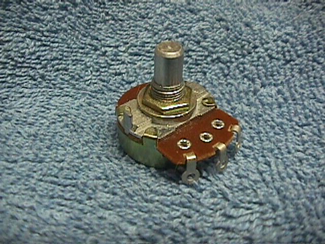
The following picture is representative of how modern pots are built. I used a carbon composition pot made by Alpha, a linear 10K, 25mm diameter control.
To get inside it, you notice those little metal tabs bent over the housing on the top? I took a fine bladed screwdriver and bent them up....
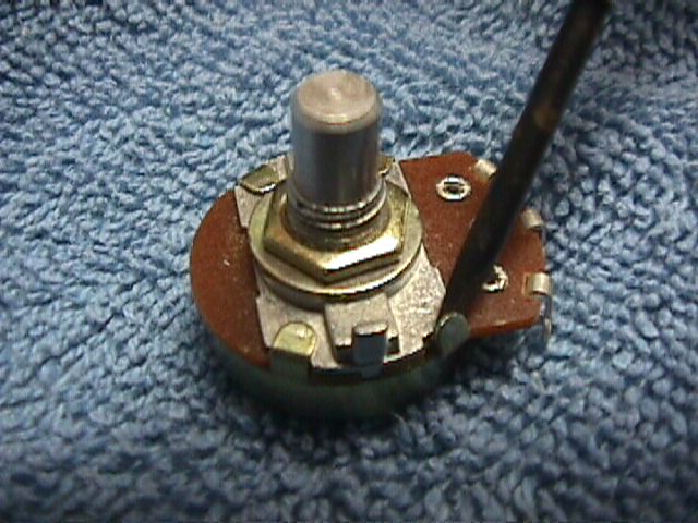
When they're all bent up, you can lift the shaft and phenolic wafer assembly out of the back housing like this.
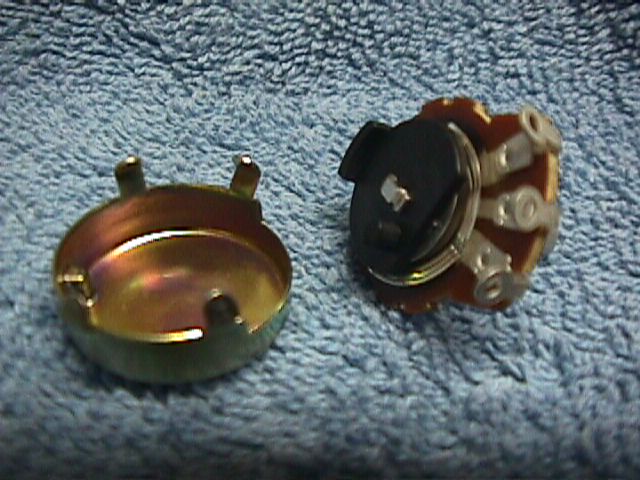
All the fun stuff appears to be inaccessible under that black plastic cover. Actually, that cover performs a couple of very useful functions; it serves to hold the wiper in place, and also interacts with the stop on the case to set the mechanical rotation limits. If you remove the tab on the plastic disk and reassemble the pot, it will now rotate freely 360 degrees. Here's a little better view of the shaft/wafer/wiper assembly.
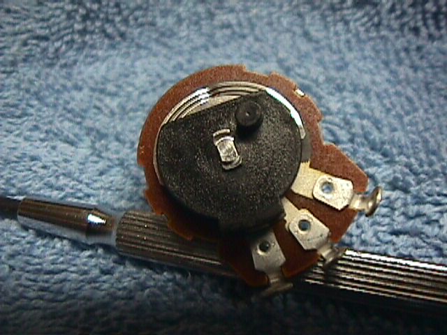
Looking closely, you can see that the shaft is held onto the plastic disk by being mechanically squashed into place. That is quick, and makes for cheap pots, but it can't be removed and successfully reassembled. That is a peculiarity of this brand, as some pots can be disassembled and reassembled successfully. In the next picture, I've used a big pair of diagonal cutters to remove the plastic disk and the metal wipers. This exposes the bare conductor assembly.
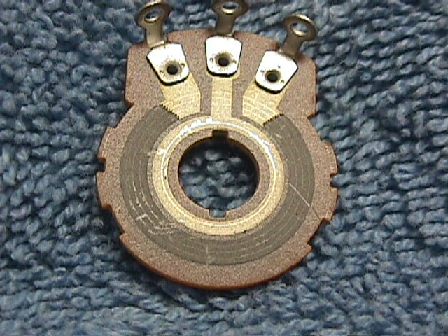
The whole works of the pot, excepting the rotating wiper are printed on the phenolic wafer. The connections to the ends of the resistive material are a conductive metal material, as is the circle of conductor that connects to the center contact. We can now begin to see our control's kinship to Ohm's variable resistors. The resistive material is a circular band of carbon-containing gunk that is printed onto the phenolic wafer, overlapping the metalization to the two outside lugs at either end. The wiper is just a sliding bridge from the center metalization ring to the outer resistive ring. The contact to the metalization is fairly reliable, but the contact to the resistive ring may be intermittent, so the connection to the outer ring is made by three contacts in parallel, as shown by the three tracks the contacts make in the top of the resistive material. Those gouges and scratches are a product of the delicate manner in which I removed the plastic wafer, so ignore those.
With this view, a couple of things fairly leap out at us. This is a linear pot, which is exactly what we should have from a continuous, homogeneous strip of resistive material. That is to say, the wiper traverses an equal amount of resistance in ohms per degree turned. If we wanted to make a non-linear pot, where the amount of resistance per degree turned were not linear, we could mess with the resistive strip to make it nonlinear. This is in fact how it's done. The strip can be made to get skinnier toward on end or the other; a narrower strip has more resistance per unit length and so the resistance per unit degree turned will change. This is not desirable from reliability reasons, as we'd still like to have three contacts to the resistive strip, and that isn't possible if the strip gets skinnier. We could also change the thickness or composition of the material from one end of the resistive strip to the other.
It turns out that printing a varying thickness is very difficult to do cheaply. Also, varying the composition in any kind of smooth fashion is very hard, not a repeatable manufacturing step. What makers of pots actually do is to use straight-line approximations to a nonlinear resistive curve, and print in sections. For instance, the first 1/3 of the circumference of the pot's resistive band may be printed with one resistive material, the second another, and the third yet another. This allows the maker to come reasonably close to some taper curve.
Other things are that we can see the way pots wear out. The wiper literally wears a path through the conductive strip. When all three contacts get all the way through, they don't make contact any more, and the pot quits functioning. During the normal life of the pot (that is, the wear-out process) the bits of resistive material gouged and work from the resistive strip stay around and can actually lift the wipers from the resistive strip. If there is a DC voltage across the pot when this happens, the wiper loses and then regains contact at a different DC level than it left, so it makes a scratch or click.
Pots used to be made with taps part way around. This was just a fourth terminal connected to a strip of metalization running under the middle of the resistive material part way round. The metalization on the ends that the wipers touch when the pot is turned all the way to one end or the other can be extended further around the path of the resistive band so that the resistive band can start later in the pot's mechanical rotation and/or end sooner. The maker can print metalization "dead zones" in the middle of the rotation where nothing much happens resistively. It's very flexible.
This simple structure means that there are lots of non-standard things we can do with pots.
You could hypothetically scrape material off the resistor band and make a higher resistance, odd taper pot, but there are better ways to do that.
There is an affliction loose in the business world that I call the MBA Disease. Old timers will recall a time when Radio Shack was really a place to get electronics parts. Radio and TV repair places had electronics parts, and distributors had a large variety of odd miscellany. You could usually find parts, even if they were not hot sellers, because the parts suppliers ordered a range of parts that they thought would appeal to their customers, and kept stock items because they were useful, even if they didn't sell for a long time.
Enter the MBA. The creed of the MBA is that everything I have in my business should be making the best return on my money *right now* and *continuously*. If some item I'm selling is not returning as good a rate of profit as some other things, I can make more money be not selling the less profitable items and concentrating on only the things that are hot sellers with high rates of return. This does work. Businesses that adopted it were more profitable than their slower peers were, and in many cases the slower peers went out of business.
These are the seeds of destruction for the electronics tinkerer, though. A lot of times tinkerers want devices that are not used in millions. This means that increasingly, it's almost impossible to find odd values, odd tapers, or unusual terminal arrangements in pots. Reverse log pots have always been a specialty item, but it's getting hard to find ordinary audio/log taper volume pots, and values that are not decade multiples of 1 or 5K are getting rare. Distributors will not stock pots that aren't high sellers; this leads to some self-fulfilling prophecy. Eventually, the manufacturers note that odd value or taper pots are not selling - pesky distributors don't order them anymore - and they quit making the odd ones. This leaves us where we are today. The manufacturers have gotten good at making a run of 10K of any pot value, any lead/leg setup, any taper, and any case. They'll happily make whatever you want, if you want enough of them. The few of us that hand solder stuff together have to make do with whatever the distributors do order. And today, that is increasing only linear pot, maybe a few audio tapers.
What is taper? It's just the ratio of the resistance already passed as the pot turns to the total resistance of the pot, described as a curve. For instance: we want to make a variable power supply with an adjustment pot that smoothly varies the voltage from one to ten volts, so we want a control that lets us do that. We have no idea whether we'll want mostly low voltages or high voltages, so we want to adjust it equally well anywhere in the range. In this case, it's most natural for the control pot to have an equal change in resistance or voltage divided per unit of rotation - we want the control to feel linear. This much of a turn is one volt, no matter whether it's near 0V or near 10V.
Volume controls are different. The human ear does not respond linearly to loudness. It responds to the logarithm of loudness. That means that for a sound to seem twice as loud, it has to be almost ten times the actual change in air pressure. For us to have a control pot that seems to make a linear change in loudness per unit of rotation, the control must compensate for the human ear's oddity and supply ever-increasing amounts of signal per unit rotation. This compensating resistance taper is accurately called a "left hand logarithmic taper" but for historical reasons has been called an audio or log pot. In these pots, the wiper traverses resistance very slowly at first, then faster as the rotation increases. The actual curve looks exponential if you plot resistance or voltage division ratios per unit of rotation.
If you used an audio/log taper pot for the control of the power supply we mentioned, the output voltage would increase very slowly at first, creeping up to maybe 10% of the final output at 50% of the pot rotation. It would then blast the other 90% in the last half of the rotation - very hard to control. Likewise, if we used a linear pot for volume control, the volume would come up dramatically in the first half of pot rotation, and then do very little change in the last half.
The dark horse taper is reverse audio, or more strictly "right hand logarithmic" taper. This taper traverses resistance very quickly at first, then more slowly as it is turned further. It's the inverse of the audio taper. This is used in some bias circuits and in controlling the speed of certain RC oscillators, which is where the audio tinkerer runs into it most.
The following diagram shows the three main kinds of pot tapers, along with one common approximation to an audio taper. Curve 1 is linear taper. If we clip one lead of our Ohmmeter (Hey! There he is again!) onto the leftmost lug, and the other lead on the center lug, then the resistance we read as we rotate the pot clockwise will fall on the curve that goes diagonally upwards. The proportion of the total pot resistance we traverse as we turn the pot is linearly proportional to the amount of rotational travel we turn.
Curve 2 shows what happens with an audio or logarithmic taper. As we turn the shaft, the proportion of resistance we traverse increases slowly at first, more slowly than the percentage of rotation. As we get past half the available rotation, the rate of resistance traversed speeds up as we get closer to the furthest rotation. This compensates for the human ear by increasing sound levels very slowly at first, then faster as the ear's sensitivity falls off at higher sound levels.
When we buy "audio taper" pots, we usually get something like Curve 3. For less expensive pots, manufacturers use a two or three-segment approximation to Curve 2. It's not perfect, but it usually works OK. Curve 4 is the typical resistance versus rotation curve for reverse log pots. In real life - that is, if you ever found one of these in real life - it is usually a two or three segment approximation, too.
If you have an unknown pot, you can figure out what taper it is. You measure the resistance from end to end, then turn the pot exactly to half its rotation and measure the resistance from the counterclockwise lug. The crosses on curves 1, 2 , and 4 show the most probable values. If the resistance is 50% of the total resistance, then the pot is linear. If you measure only 10% to 20% of the total resistance, the pot is an audio taper. If you measure 80%-90% of the total resistance, the pot is a reverse log taper.
At this point I should probably explain what a counterclockwise lug is. Of the three contacts on the pot, the wiper is easiest to pick out. If you turn the shaft fully counterclockwise, the wiper lug will show very small resistance to one of the other contact lugs. This is the counterclockwise or "cold" terminal. Turning the shaft fully clockwise, the wiper will show very small resistance to the most clockwise lug, also called the "hot" lug.
There are other tapers, but they have very specialized uses.
Our problem is this: If we need a specialized taper to recreate some effect, how do we get it if we can't go buy one? That leads us to tapering resistors.
If we set up the easiest, simplest pot to get, a linear taper pot of resistance R, and then connect a "tapering resistor" across the wiper and CCW lug, we get the situation shown in the following diagram. For clarity, I've separated the resistance above the wiper and the resistor below the wiper into two separate resistors. It makes the calculations much easier.
We're assuming the total pot resistance R is split into an R1 at the CW side and R2 on the CCW side, with R3 paralleled with R2. We'll let "a" represent the fraction of the total resistance R that the wiper has turned, and "b" be the fraction of R that R3 is. When we get out the algebra books and do the math, we find out that we can show that the ratio of output voltage to input voltage is that odd looking fraction in the picture. When we calculate out the results, we find that the divider ratio of Vout to Vin is shaped something like a true logarithmic tapered pot if we pick the right value for b. If b happens to be 1/4 to 1/5, the resulting voltage division is remarkably close to a true logarithmic pot, probably closer than a two segment approximation that we could buy! Wow! No more waiting for volume control pots!
Here's what we see when we do the math:
Unfortunately there's a gotcha in there. It's true that the voltage division ratio of this rig is arbitrarily close to that of a log taper pot. However, neither the load seen by whatever drives Vin or the source resistance as seen by the input of whatever is connected to Vout is close to what would exist for a real log pot of value R. In fact, the load on Vin varies from 1/(1+1/b)*R up to R. That means that if we're trying to do a log taper with b = 1/4, the load on Vin will be as much as 0.2* R. This may be OK, but you have to keep it in mind.
In general, if you have a voltage source that can drive a load of 1/4 to 1/5 of R and a load on Vout that has an input impedance much higher than that same 1/4 to 1/5 of R, this is a good replacement for an audio or log taper pot.
In a bit of good fortune, if you hook up the tapering resistor from the CW or hot side of the pot to the wiper, the pot emulates a reverse log pot, just as well as it did a log pot when hooked to the CCW side.
There are two ways to hook up a pot. You can hook it up as a three terminal voltage divider as we've seen above, or as a variable resistance, the two-terminal connection (sometimes called a rheostat connection for historical reasons).
In the two terminal connection, the resistance through the pot is what we're interested in, not the voltage divider ratio.
It turns out that the tapering trick works here, but only partially. If we want to make a reverse log tapering pot, we're in! However, there is no way to get a simulation of a log taper pot in the two terminal connection. For that we have to buy real audio taper pots.
Here's what you get if do the series resistor connection:
Note that the CW terminal is unused. This is usually tied to the wiper, although that is not seen here. You can't simply put the tapering resistor from the CW terminal to the wiper and get a log taper pot emulation, like you could with the voltage divider connection. That just gives you the reverse of this graph, with the resistance starting to decrease slowly and then faster. The two terminal connection is non-polar; it looks the same however you hook it up. The only thing that changes is which end of the graph you start from.
In the math examples I left b, which is the fraction of the pot resistance that the tapering resistor is, as a parameter rather than making it a fixed ratio. Usually, people pick a value of b of about 4 or 5. Those curves are close to the classical mathematical description of a log or reverse log pot. I left b a parameter to show you that you can make your own taper by selecting a different value of b. For a semi-log taper, use a b of about 2.
I'm tired of typing. I'll put in more later. As always, additions and corrections are welcome. Send'em in!