Copyright 2000 R.G. Keen. All rights reserved. No permission for serving from web sites other than http://www.geofex.com.
Aaaacccckkkk!!! Why would anyone even think of letting solid state parts creep into their virtuous tube amplifier?? That's consorting with the devil, isn't it?
Maybe. What we want tubes for is how they sound as amplifiers. There are some other things that tubes are and have been used for that just maybe might be as well served by solid state parts, given that we do this carefully and test the tone each time. At the first glimpse of the silicon monster raising it's head, we can excise the tonal sins, recognizing that we've gone too far. Maybe our musical souls would come through intact.
I guess it will come as a surprise to some people that there are any things in a tube amp that can be done by a solid state part without adding ugliness to the amp's tone - in fact, there will in all likelihood be people who refuse to believe this at all, and will be morally offended at the suggestion. If you're one of these, quit reading this now and save your time and outrage. A mind is a terrible thing to close.
Where to NOT put MOSFETs in a tube amp.
In general, not anywhere that you count on for gain or distortion. Since different tube amps have different places where distortion is generated, accounting for the wide difference in sounds between amps, this can be a tricky thing to determine. Furthermore, even followers can make a difference in tone by providing enough drive to push a following tube stage into positive grid operation. This can soften distortion or make it harsher, depending on the particulars of the circuit.
What kinds of things might we do with silicon parts?
First, we'll limit ourselves to MOSFET parts. Bipolar transistors do many things well, but are not in general good for tube amp use. MOSFETs have characteristics very much like monster pentodes anyway, so we may be able to do some good things.
Second, we'll reserve all the voltage gain stages for tubes. This keeps the tube-iness where it can be heard. This leaves only followers and power supply functions for the MOSFETs.
First application: Source Follower to replace Cathode Follower.
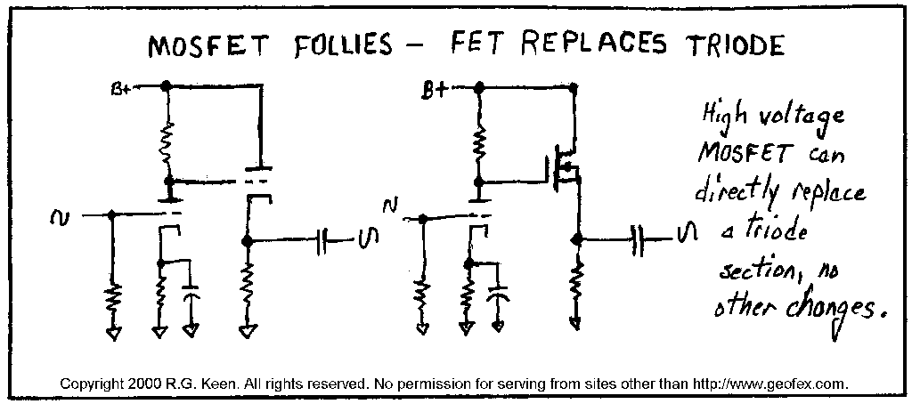
Many amps use tubes for cathode followers to buffer the plate of a triode for more drive capabilities. The most common is Marshall's use of a cathode follower to drive their tone stack. The cathode follower is hooked up with the plate to the local B+ supply, the grid to the plate of the driving tube, and the cathode to ground through a resistor. The signal is taken from the cathode through a capacitor. This connection works well and drives the tone stack hard, but is hard on the tube, as the heater of the tube is usually kept at ground potential and the cathode is some 100 to 200V higher than ground. All indirectly heated tubes have a maximum voltage rating for the insulation between the heater and cathode, most of the 300V. With any largish signal, the Marshall cathode follower is very close to this.

However, if we use a MOSFET that can take the voltage, we can literally replace the triode section in the follower with the MOSFET, connecting drain for the plate and source for the cathode. The gate is connected to the preceding plate through a 220 ohm gate-stopper resistor. No other changes are needed! A 12AX7 triode will bias with the cathode about 1V more positive than the preceding plate; a big MOSFET like an IRF820 will bias with the source about 2V more negative than the preceding plate - the 3V difference is utterly inconsequential.
"But wait!" I hear you yell. "The MOSFET has a big gate-source capacitance. Won't that suck all the high frequencies out of the signal?".
No, it won't. The big gate-source capacitor is there, OK, but when the device is hooked up as a follower, the apparent capacitance seen by a circuit driving the MOSFET gate is reduced to a very small level by the fact that the source is following the gate almost perfectly, so the apparent capacitance is reduced by the local feedback to an inconsequential level. Even a high impedance 12AX7 plate is not affected in the audio range by this capacitance. Even the big power, big capacitance MOSFETs do this one OK. I have done this, and what's more, done the necessary measurements to find the effect on the response of the composite stage - and there is no detectable change in frequency response below 30kHz. None.
This squares with the empirical evidence of listening to it - it sounds the same as when a triode is used as a cathode follower.
Zetex makes a TO-92 package MOSFET worth some consideration for replacing 12AX7 followers. It is a 450V/0.07A device with the type number ZVN0545A. You can find the full data sheet at ftp://www.zetex.com/data_books/thru.hole/zvn0545a.pdf. The gate-source capacitance on this one is considerably smaller than the bigger power MOSFETs, and it should perform very nicely indeed as a follower as long as the power dissipation of the package (700mw) is not exceeded.
The MOSFET does have some differences from a tube follower. The MOSFET will still be linear when the preceeding plate has bottomed out; a typical 12AX7 triode section just can't "saturate" in normal operation to much less than 50V. When the driver tube is saturated, the MOSFET follower is still happily linear. The MOSFET can also get within a few volts of the B+ line, which is much better than the triode section it replaced could do - the triode could only get within about 50V of the B+ level. So the MOSFET will be linear for a wider range of signals than the tube it replaces. Some amps use the triode cathode follower to generate distortion. If your amp is one of those, the MOSFET will NOT generate distortion like the triode did. The MOSFET will accurately reproduce whatever the amplifying tubes send it. In most amps, the fact that there is a MOSFET there instead of a triode will not be audible. I have personally done this mod, and I can detect no hint of harsh solid state sound; no one I've asked for the opinion can either.
Source Follower Drive for Output Tubes
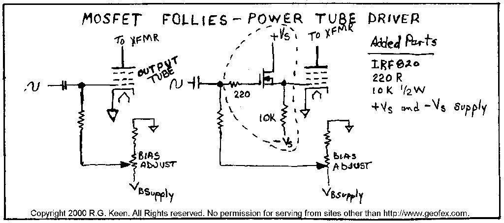
Another place MOSFETs can be used as followers is as follower drivers for output tubes. When output tubes are overdriven, their grids are often driven positive. If the coupling to the grids is by capacitor, this can lead to grid blocking/ bias shift as the grid current skyrockets when the grids go positive. This current builds up as a negative charge on the coupling capacitors and causes the tube to effectively be biased more negative (towards class B) than the static bias setting. So on overdriven notes, the output tubes are pushed into a harsh-sounding crossover distortion. In addition, the usual 12AX7 or 12AT7 phase inverter plate impedance is so high that it can't pull the output tube grid positive in the face of grid current, so the grid of the output tube is hard-clipped at Vgk=0V. This clipping can be as harsh as any solid state situation.
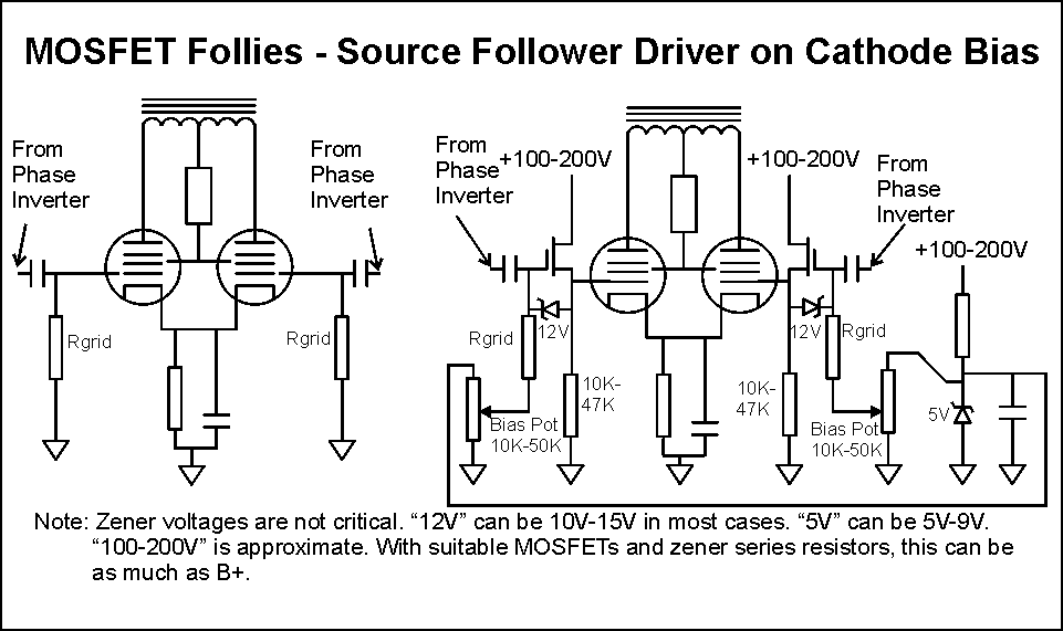
The solution to the class B bias shift and grid current clipping is to drive the output tube grids direct coupled from a cathode follower. The follower is set up so that its cathode sits at the normal negative bias voltage of the output tube, maybe -10V to -40V depending on the tube type. This means that the cathode resistor is tied to a more negative voltage of something more than twice the bias voltage, so it can pull the output tube grid negative. The grid of the source follower is connected where the output tube grid used to be, to the bias voltage source through large resistors and through capacitors to the phase inverter. The plate is connected to a postive voltage high enough to allow full signal operation at the cathode and low enough not to damage the tube.
The phase inverter cannot drive the grid of the cathode follower positive with respect to its own cathode, as its cathode follows the grid up, and we have supplied enough power supply voltage to the follower so it doesn't run out of volts. The cathode can drive the grid of the output tube positive and has a low enough impedance to pull the grid positive in the face of grid current. The grid current is "eaten" by the follower, so it does not cause bias shift into class B crossover distortion nor grid current limiting distortion. The output tube can now be driven into plate saturation, which is much softer than grid current limiting.
Cathode follower drivers for output tubes are hardly ever used, largely for economic reasons. It's expensive to put an extra tube in to do that. However, we can once again use power MOSFETs to do the job. Again, the MOSFET drops right in, drain for plate, gate for grid, source for cathode. An IRF 820 has both enough voltage rating and more than enough current and power ratings to do the job. And the IRF820 is about $2.00 each, doesn't need heater current, and won't wear out like a tube will.
A couple of amp builders have written up their experience with this mod at the Ampage discussion board. The results were uniformly good - no hint of "solid state sickness" in the sound, just a sweetness and an increase in apparent amplifier power.
Although it's a little harder, you can also do this for cathode biased amps. You have to not only generate a negative voltage for the sources to work from, but also include a "MOSFET bias" for each of the MOSFETs. Here's why: the mosfets we're using have a turn-on voltage of between 1 and 5 volts before they start conducting any thing at all. If we just popped them into the cathode biased setup, the Vgs would effectively be subtracted from the voltage on the cathode resistor. While the inherent feedback in the cathode biased setup would correct some of this, we'd like to have no change in the output tube biasing at all from the MOSFET use. All you need is a couple of pots to bias the MOSFET gates a little positive. Five volts will be enough, and this can be had from B+ through a 5V zener. The gates are connected to the wiper of a bias pot across this 5V supply and this can pull the gate just enough positive to counteract the loss in voltage with Vgs.
A MOSFET Standby Switch
A MOSFET makes an almost ideal switch for DC currents. Instead of using a mechanical switch that can is both expensive and probably not rated to handle the voltages involved in switching B+ off, we can instead take note that at the cathodes of the output tubes, we could just open the cathodes, or even better, insert a high resistance. The high resistance lets the tubes self-bias to the edge of being completely off, and the switch doesn't need to be floating at B+. Even better, we use a power MOSFET to be the switch.
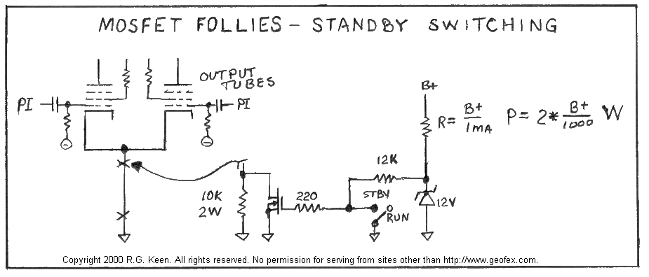
The recipe is simple. Where your output tubes' cathode circuits connect to ground, break that connection. Insert a 10K 3-5W resistor to ground. Across that resistor connect the drain-source of a high voltage MOSFET rated for at least 100V more than your B+ a the first filter cap. This may require 700 to 1kV MOSFETs - which are readily available! Place a 220 ohm 1/4W resistor in series with the gate *right at the gate lead* and then tie the 220 ohm resistor though 10K to a +12V source. The "standby switch" is a small toggle switch that shorts the junction of the 220 and the 10K resistor to ground. When that happens, the MOSFET is switched off, and the 10K appears in series with the tubes' cathodes. The tubes self-bias off -dramatically off, but with a tiny trickle of current still flowing. They stay hot and ready, and the trickle keeps the tubes from being damaged by the held-off condition. The 12V source is a zener fed by a large resistor from B+ that feeds a fraction of a milliamp to the zener.
When the standby switch is open, the gate of the MOSFET is pulled to +12V by the 220 ohm and the 10K resistor. This turns it fully on, and it saturates to a few ohms. This shorts out the 10K resistor and lets the output stage operate normally. The MOSFET looks like a real resistor, and so does not cause any tonal aberrations.
A MOSFET B+ Reducer
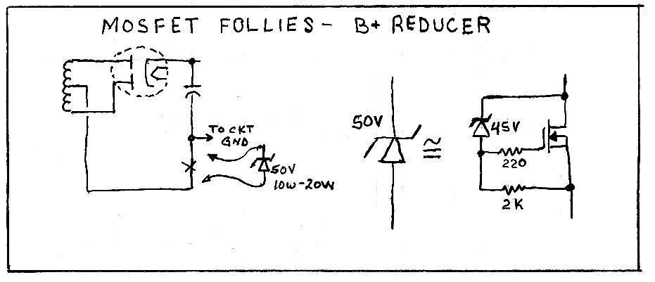
Sometimes you just want the B+ voltage on an amp to be smaller than it is. This can often happen when you're working with an existing set of transformers and want to use different output tubes or limit dissipation on the tubes. A common way to do this is to use a power Zener in series with the center tap of the power transformer. The zener voltage is directly subtracted from the resulting B+. It's fairly common to want to reduce the B+ by about 50V.
However, a 50V zener will need to be rated at 10-20 watts to do this job. These can be expensive. You can do much the same thing by using a power MOSFET with a low power zener to make an "amplified zener". The power zener is replaced by a low power zener that sets the voltage on the gate of a MOSFET. The MOSFET conducts the vast majority of the current, an so is the device that absorbs the waste heat. Notice that you MUST use a power MOSFET that has a large enough power rating - which isn't hard at all, as 75W MOSFETs cost about $2.00 - and you MUST provide the MOSFET a suitable heat sink to remove the heat.
A MOSFET Phase Inverter
Coming...