Copyright 2000 R.G. Keen. All rights reserved. No permission for serving from
sites other than http://www.geofex.com.
FXBus is a trademark of GEO Fex Cybernetic Music, used by permission. Permission
granted for individual, non-commercial use of FXBus materials posted here. All
other uses subject to licensing fees and restrictions. Use GEO's feedback reply
for licensing information.
| Making a FXBus 1 Motherboard] | [FXBus Module 1] - Buffer/ Gain/ Booster Module - 50 ways! | [FXBus Module 5] a feedback diode clipper like the TS | [FXBus Module 10] an opamp driven shunt diode clipping stage |
| [ FXBus 1 Module Layouts and Schematics] | [FXBus Module2] - A two JFET Mu amp | [FXBus Module 6&7] a two-fer! splits the Dr. Q into a filter and envelope section | |
| [FXBus Module 3]a tube amp style tone/volume stack | [FXBus Module 8] a Big Muff style tone control | ||
| [FXBus Module 4] a Fuzz Face style clipping stage | [FXBus Module 9] a Big Muff style clipping stage |
Like to build guitar effects? Want a cleaner way to experiment than perfboarding each new one? You'll love FXBus.
I noticed that all the effects I build have many of the same features - a box, a bypass switch, controls, maybe a bias supply to split 9V to 4.5V for a reference, power supply decoupling, and so on. I've come to think of a lot of the common stuff as a "wrapper" that encloses the circuits that actually do the work and make it easy to get signals into and out of them.
In the engineer's part of my brain, when I'm designing effects, I think in terms of functional modules - this section of the circuit amplifies, this part does tone control, this piece extracts the envelope, and so on. It occurred to me that I could actually marry the two concepts in a kind of standard bus arrangement that would at the same time be easy to work with but very flexible for experimenters.
What's a FXBus?
It's a standard arrangement of signals and interconnections that make it easy to interconnect effects or sub-effect modules. There are at least three levels of FXBus I've defined, that I'll get posted as I go. Let's look at the basics.
Module Basics
Every effect I've ever seen can be sliced up (conceptually at least) into one
or more modules. A module is a subfunction of the effect that does
one main thing in the effect and maybe sets up certain conditions that are
useful for its own operation or the operation of other pieces of the effect. For
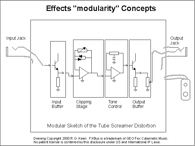
example, look at this conceptual schematic: 
The drawing is of the well-known Tube Screamer family, and does not include a lot of details like coupling capacitors, power supply and so on so we can focus on the modular nature of the design.
There are four major modules in the TS series. These are an input buffer, a clipping stage, a tone control, and an output buffer. The input buffer is simple - it just accepts the input signal from the input jack, and presents a high input impedance (that is, very little loading) as possible to the input signal. It buffers the signal to drive the rest of the effect. It is, in effect, an amplifier with a gain of one, and no controls of any kind. I've left out the input capacitor, which helps filter out low bass signals.
The clipping stage is next in line. It does a couple of things. It clips the signal, but it does it by a variable amount, as shown by the variable feedback resistor around the opamp, so it has one control. Not shown is some frequency response shaping, or EQ. This is covered in detail in "The Technology of the Tube Screamer" if you want to dig further.
The tone control stage receives the clipped signal from the clipping stage and applies a variable amount of treble boost or bass boost, as shown by the variable tone control resistor.
Finally the output buffer stage lets the user vary the signal level from the tone control stage and then buffer it to drive signals to the output jack and any following things connected to it. Notice that in theory at least, the pieces are just strung together like stacking alphabet blocks from end to end.
If we had a full set of basic modules, we could create any effect by just hooking up enough pieces in the right order.
Like all generalities, there are some conditions attached to that. Here are some of the things that let us just daisy chain things together:

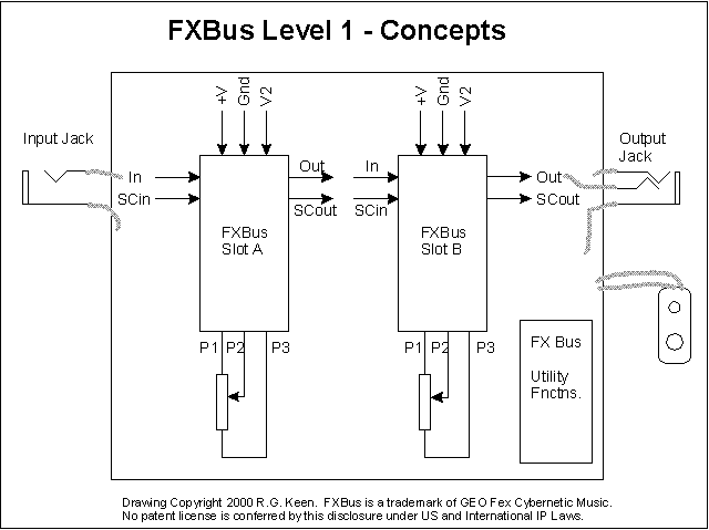
So when we gather this mess up a bit, we come up with something like the FXBus Level 1. The definitions of modules in FXBus1 allow for several modules enclosed in a "wrapper" that supplies all the "life support" items like input/output jacks, bypass switching, power supply voltages, and so on. The modules have provision for one input/output per module, one control pot per module, and one side chain input/output per module.

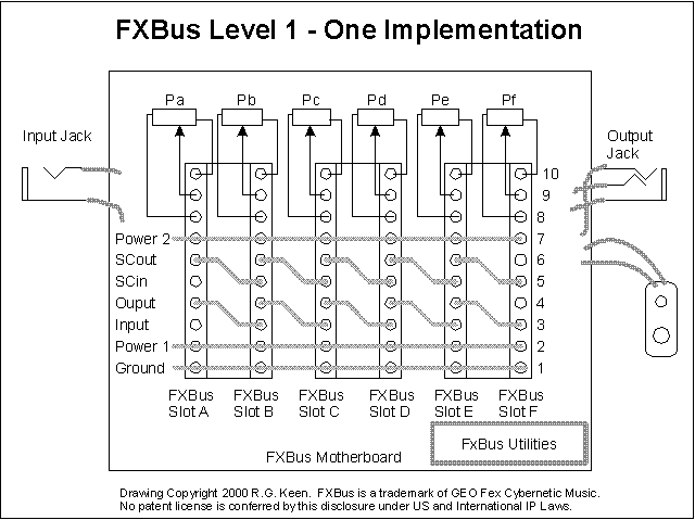
A practical way to implement a basic FXBus 1 might look like this. The basic module plugins should be both electronically and physically small. A FXBus 1 bus needs only ten I/O connections:
While the exact connector does not matter, it is convenient and cheap to use something like a 20 pin DIP socket for the connections between the module itself and the "motherboard", with ten pluggable legs on the module to mate with the socket. This gives a setup that is easy to make, small and easily set up in a reasonable-sized effect box. The sketch shows one way that you might lay out a motherboard PCB. The sockets making up the motherboard connectors are connected so that every output is chained to the next input, and every sidechain output is tied to the next sidechain input. There are two paths from each module to the next, allowing for some interesting possibilities.

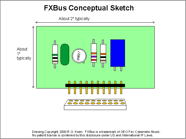
A typical FXBus 1 module might look something like this sketch. There's a section of header pins (like Mouser part number 151-8432) to plug into a 20-pin DIP sockets we've co-opted as a bus connector, some parts that make up the module circuitry (like maybe a whole Dallas Rangemaster clone - it's simple enough!) and the socket it plugs into, which is part of the FXBus motherboard. Note that the FXBus board plugs into only one side of the two-row socket. A single 20 pin DIP socket makes two FXBUS connectors. The board can be perfboard, or a PCB.
Using dimensions like this, it should be possible to eight or more modules into a Hammond 1590BB cast aluminum enclosure as long as you didn't insist on having a pot on every module, which is reasonable. There are some tricks that can make this a VERY flexible setup for testing effects ideas. In fact, it approaches an effects micro-synthesizer in design. A couple of FXBus setups in parallel could be very interesting indeed!
So how do side chains figure into this?
A very simple example of a side-chain module might be a tremolo. A tremolo consists of a main signal path through the device, and a no-inputs side-chain that supplies the Low Frequency Oscillator signal that modulates the signal. A fully-modular tremolo design might use an input buffer, a modulation stage, an LFO stage, and an output buffer.
Another simple side-chain effect is a compressor. A compressor is an input stage/buffer, a modulation stage with a variable gain, and a side-chain stage that accepts the input signal as a side-chain input, and which has as an output the control voltage to the modulation stage that makes the signal output be compressed.
A phaser is a phase shift module (if you can get all of them into one module) or several modules strung together with a sidechain modulation that is usually an LFO. Some phasers can use the envelope of the signal itself as a modulation signal, so it's a loudness sensitive phase shift. If you took a wah module and fed it a sidechain signal of the envelope of the signal, you get an auto-wah like the Mutron. Take the same wah module and feed its sidechain input a LFO, and you get --- well, something there's not a word for yet. You begin to get the idea - this stuff is FLEXIBLE! How about a distortion where the distortion is controlled by a LFO? An envelope?
Modularity and Elegance
I can hear a chorus of objections from those of you who have done some design before. You'll be thinking, "Yeah, you'll need eight modules to get a tube screamer in a box if you put in a buffer, then a clipping stage, then a tone stage, then an output stage, and have to make each stage have AC coupling caps, high input impedance, low output impedance, and so on! Why not just condense the design so the extra parts you don't need are not there?"
That's a good question. The answer lies in the mental process involved in
design itself, as divorced from the particulars of electronics (or any other
specific discipline.) In designing , everyone I've been closely acquainted with
to know their internal mental design processes works one or both of two ways -
top down or middle out. They then do a "polishing" pass that combs out
extraneous parts, takes advantage of the special features of the sections of the
design to get rid of things if possible, and then maybe collapses two or more
functions into a single stage where possible. Good designers generally DON'T do
a front-to-back design, starting and going linearly through the whole design,
and they don't usually do a "bottoms up"
design, working from the lowest level of optimization back up to the whole
thing.
The process of designing from top down is particularly effective. It lets you concentrate on what you want to get done, then polish up the places that are rough. A good example might be Jack Orman's "Son of Screamer" design. I'd be willing to bet that Jack started with the basic TS-9 schematic and then started eliminating things that he reasoned could be removed without changing the overall function. He kept only the parts that were really needed in each "module" and dispensed with "modules" that were not needed. This left a design that functioned pretty much the same as what he started with, but which used fewer parts - more "elegant" by at least one meaning of the word.
Which brings us around to elegance. Elegance in design usually means having just the parts that are needed, without extra parts, decoration, or confusion that performs the desired functions well. Elegant design is highly sought after in engineering. Every elegant design I've ever seen started as either an unexpected flash of brilliance (which just means that the person's unconscious mind put it all together first) or as a top down design that was polished to elegance. I view modularity, with the redundance that will inevitably creep in, as but one step on the path to elegance. That's why I titled this "Modularity and Elegance", not "Modularity versus Elegance". They are not opposites.
A FXBus 1 motherboard is easy to make from commonly available parts. You can perfboard it, wire wrap it, and so on. However, I like this method. The full-sized toner transfer pattern for a FXBus 1 mother board can be printed directly to a toner sheet and then ironed onto copper clad and etched. This pattern goes on the TOP or COMPONENT side of the board, and the components are mounted to the surface with solder. The IC sockets have their pins bent out sideways to be soldered. This leaves the back side completely bare of components, so it may be used for mounting with double sided tape. The motherboard is laid out conceptually as shown in the diagram "FXBus - Level 1 Implementation". It adds pads to get signals onto and off the motherboard, power connections, a bias voltage resistor layout, and pads for all the pot connections as well as a power decoupling capacitor position.
FXBus 1 Module Layouts and Schematics
Here's the first batch - printable toner transfer sheet patterns for a motherboard, and modules for:
Other Modules to come - think about what modules YOU could put in there!